|
|
|
|
1
|
|
2
|
|
3
|
Click Add.
|
|
4
|
Click
|
|
5
|
In the Select Study tree, select Preset Studies for Selected Physics Interfaces>Optimization>Topology Optimization, Stationary.
|
|
6
|
Click
|
|
1
|
|
2
|
|
1
|
|
2
|
|
3
|
|
4
|
|
1
|
|
2
|
|
3
|
|
1
|
|
2
|
|
3
|
|
4
|
|
1
|
In the Model Builder window, under Component 1 (comp1)>Geometry 1 right-click Work Plane 1 (wp1) and choose Extrude.
|
|
2
|
|
1
|
|
2
|
|
3
|
|
4
|
|
5
|
|
6
|
|
1
|
|
2
|
|
3
|
|
4
|
|
5
|
|
1
|
In the Model Builder window, under Component 1 (comp1) right-click Solid Mechanics (solid) and choose Roller.
|
|
1
|
|
3
|
|
4
|
|
1
|
|
3
|
|
4
|
|
5
|
|
1
|
|
2
|
|
3
|
|
1
|
|
2
|
|
3
|
|
1
|
|
2
|
|
1
|
In the Model Builder window, under Component 1 (comp1)>Topology Optimization click Density Model 1 (dtopo1).
|
|
2
|
|
3
|
|
4
|
|
5
|
|
1
|
|
2
|
|
3
|
|
4
|
|
5
|
|
6
|
|
7
|
|
8
|
|
1
|
|
2
|
|
3
|
|
4
|
|
5
|
Locate the Variables section. In the table, enter the following settings:
|
|
1
|
In the Model Builder window, under Component 1 (comp1)>Solid Mechanics (solid) click Linear Elastic Material 1.
|
|
2
|
|
3
|
|
1
|
|
2
|
|
3
|
|
1
|
|
2
|
|
3
|
|
4
|
Locate the Constraints section. In the table, enter the following settings:
|
|
5
|
|
6
|
|
7
|
|
1
|
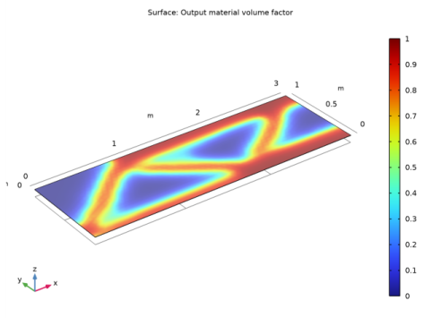
In the Model Builder window, expand the Results>Topology Optimization>Output material volume factor node, then click Surface 1.
|
|
2
|
|
1
|
|
2
|
|
3
|
|
1
|
|
2
|
|
1
|
|
2
|
|
3
|
|
4
|
|
1
|
|
2
|
|
3
|
|
4
|
|
5
|
|
6
|
|
7
|
|
8
|
|
1
|
In the Model Builder window, under Global Definitions>Mesh Parts right-click Mesh Part 1 and choose Build All.
|
|
2
|
|
1
|
|
2
|
|
3
|
Locate the Selections of Resulting Entities section. Select the Resulting objects selection check box.
|
|
4
|
|
1
|
|
2
|
|
3
|
|
4
|
Locate the Distances section. In the table, enter the following settings:
|
|
5
|
|
1
|
|
2
|
|
3
|
|
4
|
|
5
|
|
6
|
|
7
|
|
1
|
|
2
|
|
3
|
|
4
|
|
5
|
|
6
|
|
7
|
|
8
|
|
9
|
|
10
|
|
1
|
|
2
|
|
3
|
|
4
|
|
5
|
|
6
|
|
7
|
|
8
|
|
9
|
|
1
|
|
2
|
|
3
|
|
4
|
|
5
|
|
1
|
|
2
|
|
3
|
|
4
|
|
5
|
|
6
|
|
1
|
|
2
|
|
3
|
|
4
|
|
5
|
|
6
|
|
7
|
Click OK.
|
|
1
|
|
2
|
In the Settings window for Adjacent Selection, type Moving Boundaries Edges in the Label text field.
|
|
3
|
|
4
|
|
5
|
|
6
|
|
7
|
Click OK.
|
|
1
|
|
2
|
|
3
|
|
4
|
|
5
|
|
6
|
|
1
|
|
2
|
|
3
|
|
4
|
|
5
|
In the Add dialog box, in the Selections to invert list, choose Moving Boundaries and Load Boundary.
|
|
6
|
Click OK.
|
|
1
|
|
2
|
|
3
|
|
4
|
Click
|
|
5
|
|
6
|
Click OK.
|
|
7
|
|
8
|
|
1
|
|
2
|
In the Settings window for Intersection Selection, type Moving Boundaries Lower Edges in the Label text field.
|
|
3
|
|
4
|
|
5
|
In the Add dialog box, in the Selections to intersect list, choose Symmetry z Edges and Moving Boundaries Edges.
|
|
6
|
Click OK.
|
|
1
|
|
2
|
|
3
|
|
4
|
|
1
|
|
2
|
|
3
|
|
4
|
|
1
|
|
2
|
|
3
|
|
4
|
|
5
|
|
6
|
Click OK.
|
|
1
|
|
2
|
|
3
|
|
4
|
|
1
|
|
2
|
|
3
|
|
4
|
|
1
|
|
2
|
|
3
|
|
4
|
|
5
|
|
6
|
Click OK.
|
|
1
|
|
2
|
|
3
|
|
4
|
Find the Physics interfaces in study subsection. In the table, clear the Solve check box for Topology Optimization.
|
|
5
|
|
6
|
|
7
|
Click to expand the Dependent Variables section. In the table, clear the Solve check box for Topology Optimization.
|
|
8
|
|
9
|
|
1
|
|
2
|
|
3
|
|
4
|
|
5
|
|
6
|
|
7
|
|
1
|
|
2
|
|
1
|
|
2
|
|
3
|
In the table, clear the Solve for check boxes for Control Variable Field 1 (movex) and Control Variable Field 2 (movey).
|
|
1
|
|
2
|
|
3
|
|
4
|
|
5
|
|
6
|
|
7
|
|
8
|
In the Dependent variables table, enter the following settings:
|
|
1
|
|
2
|
|
1
|
In the Model Builder window, under Component 2 (comp2)>Coefficient Form Edge PDE (ce) click Coefficient Form PDE 1.
|
|
2
|
|
3
|
|
4
|
|
5
|
Locate the Absorption Coefficient section. In the a text-field array, type 1 in the first column of the first row.
|
|
6
|
|
7
|
|
8
|
|
1
|
|
2
|
|
3
|
|
4
|
|
1
|
|
2
|
|
3
|
|
4
|
|
1
|
|
2
|
|
3
|
|
1
|
|
2
|
|
3
|
|
4
|
|
5
|
|
6
|
|
7
|
|
8
|
|
1
|
|
2
|
|
3
|
|
4
|
|
5
|
Locate the Variables section. In the table, enter the following settings:
|
|
1
|
|
2
|
|
3
|
|
1
|
In the Definitions toolbar, click
|
|
2
|
In the Settings window for Prescribed Normal Mesh Displacement, locate the Boundary Selection section.
|
|
3
|
|
1
|
In the Definitions toolbar, click
|
|
2
|
|
3
|
|
4
|
|
1
|
|
2
|
|
3
|
|
1
|
|
2
|
|
3
|
|
1
|
|
2
|
|
3
|
|
4
|
|
1
|
|
2
|
|
3
|
|
4
|
|
5
|
|
1
|
|
2
|
|
3
|
|
1
|
|
2
|
|
3
|
|
4
|
|
1
|
|
2
|
|
1
|
|
2
|
|
3
|
Find the Physics interfaces in study subsection. In the table, clear the Solve check box for Solid Mechanics (solid).
|
|
4
|
|
5
|
|
6
|
|
7
|
|
1
|
|
2
|
|
1
|
|
2
|
|
1
|
|
2
|
|
3
|
|
4
|
|
5
|
Click Replace Expression in the upper-right corner of the Objective Function section. From the menu, choose Component 2 (comp2)>Solid Mechanics 2>Global>comp2.solid2.Ws_tot - Total elastic strain energy - J.
|
|
6
|
Locate the Objective Function section. From the Objective scaling list, choose Initial solution based.
|
|
7
|
Locate the Control Variables section. In the table, clear the Solve for check box for Density Model 1 (dtopo1).
|
|
8
|
Click Add Expression in the upper-right corner of the Constraints section. From the menu, choose Component 2 (comp2)>Definitions>Nonlocal couplings>comp2.intop1(expr) - Integration 1.
|
|
9
|
Locate the Constraints section. In the table, enter the following settings:
|
|
1
|
|
2
|
|
3
|
|
4
|
|
1
|
|
2
|
|
3
|
|
4
|
|
5
|
|
1
|
|
2
|
|
3
|
|
4
|
|
1
|
|
2
|
|
3
|
|
4
|
|
5
|
|
6
|
|
7
|
|
8
|
|
1
|
|
2
|
|
3
|
|
1
|
|
2
|
|
3
|
|
4
|
|
5
|
|
1
|
|
2
|
|
1
|
|
2
|
|
3
|
Select the Plot check box.
|
|
4
|
|
1
|
In the Model Builder window, expand the Shape Optimization>Solver Configurations>Solution 2 (sol2)>Optimization Solver 1>Stationary 1>Segregated 1 node.
|
|
2
|
|
3
|
|
4
|
|
5
|
|
6
|
In the Add dialog box, select Material mesh displacement (comp2.material.disp) in the Variables list.
|
|
7
|
Click OK.
|
|
8
|
|
1
|
In the Model Builder window, under Results, Ctrl-click to select Applied Loads (solid), Applied Loads (solid2), and Topology Optimization 1.
|
|
2
|
Right-click and choose Delete.
|
|
1
|
|
2
|
|
3
|
|
4
|
|
5
|
|
1
|
|
2
|
|
3
|
|
4
|
|
5
|
|
1
|
|
2
|
|
3
|
|
1
|
|
2
|
|
3
|
|
4
|
|
5
|
|
6
|
|
7
|
|
1
|
|
2
|
|
3
|
|
4
|
|
5
|
|
6
|
Locate the Scale section.
|
|
7
|
|
8
|
|
1
|
|
2
|
In the Settings window for 3D Plot Group, type Stress (solid) Topology Optimization in the Label text field.
|