|
|
|
|
1
|
|
2
|
Click
|
|
1
|
|
2
|
|
3
|
|
1
|
|
2
|
|
3
|
Click
|
|
4
|
|
5
|
|
6
|
Click
|
|
1
|
|
2
|
|
1
|
|
2
|
|
3
|
|
4
|
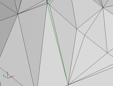
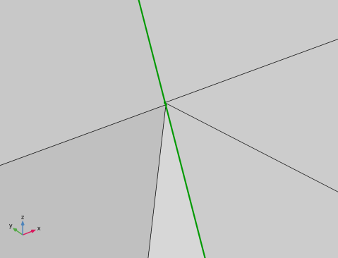
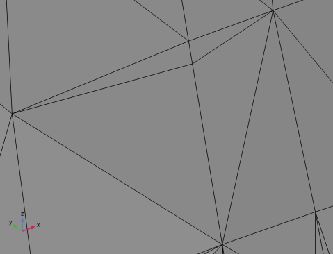
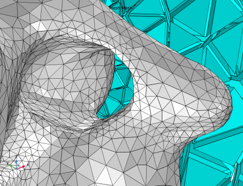
In the list, select 3 (the edge located in the upper right corner of the previous image).
|
|
5
|
|
6
|
|
1
|
|
2
|
|
3
|
|
4
|
|
5
|
|
6
|
|
7
|
|
1
|
|
2
|
|
3
|
|
4
|
|
5
|
|
6
|
|
1
|
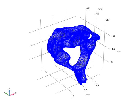
In the Model Builder window, expand the Component 1 (comp1)>Mesh 1>Import 1>Information node, then click Information.
|
|
2
|
|
3
|
|
4
|
|
5
|
|
1
|
|
2
|
|
3
|
|
4
|
|
1
|
In the Model Builder window, expand the Component 1 (comp1)>Mesh 1>Fill Holes 1>Information node, then click Information.
|
|
2
|
|
3
|
|
4
|
|
5
|
|
1
|
|
2
|
|
3
|
|
4
|
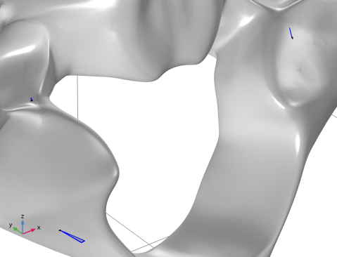
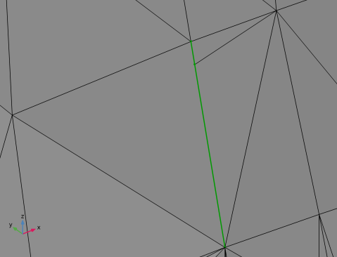
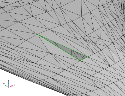
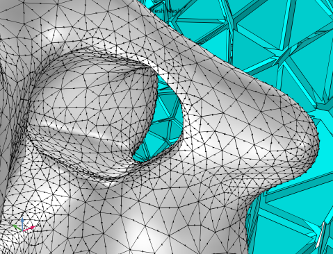
In the Perimeter text field, type 2.3[mm]. The value you enter here should be slightly larger than the measured hole perimeter.
|
|
5
|
|
1
|
|
2
|
In the Combine Geometry with Mesh dialog box, , you get the question if you want to combine this geometry with the mesh in Mesh 1. If you don’t want to do this or don’t want to decide at this point, you can just click Cancel and decide what to do with the geometry at a later stage. In this tutorial, we want to combine the geometry of the block with the mesh of the vertebra, so let us look at the options of how to do this.
|
|
-
|
Add an Import node to Mesh 1. This will import a surface mesh of the geometry to the meshing sequence, where the two will be combined. This is what we intend to do in this tutorial and the option we will use.
|
|
-
|
Add a new meshing sequence which is conforming to the geometry and an Import node in Mesh 1 where the mesh of the geometry is imported. Use this option if you want full control over the mesh you import into Mesh 1.
|
|
3
|
Click OK to confirm the first option.
|
|
4
|
|
5
|
|
6
|
|
7
|
|
8
|
|
9
|
|
10
|
|
1
|
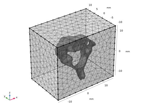
In the Model Builder window, under Component 1 (comp1)>Mesh 1 right-click Import 2 and choose Build Selected to import a Normal sized surface mesh of the block.
|
|
2
|
|
3
|
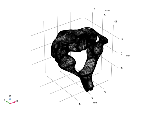
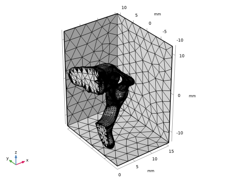
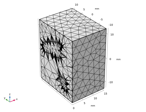
Rotate the mesh in the Graphics window to check that the vertebra is fully contained in the block, the two meshes should not intersect. Click the Go to Default view button.
|
|
4
|
|
5
|
|
6
|
|
7
|
|
1
|
|
2
|
|
3
|
|
4
|
|
5
|
|
1
|
|
2
|
Go to the Home tab.
|
|
3
|
|
1
|
|
2
|
|
3
|
|
1
|
|
2
|
In the Settings window for Delete Entities, click
|
|
3
|
|
4
|
|
5
|
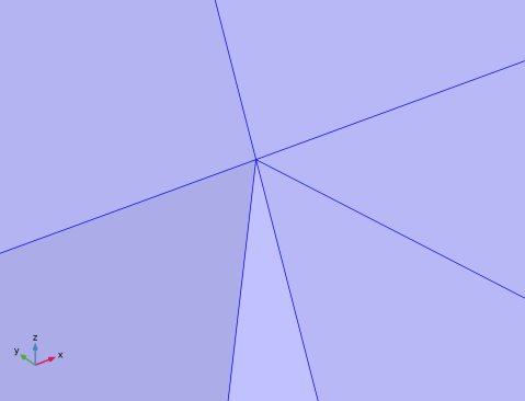
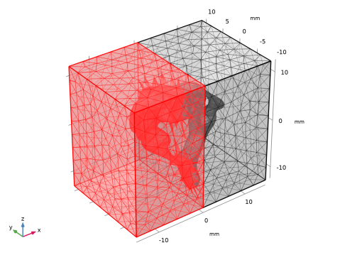
In the Selection list, confirm that you have the expected nine boundaries; six for the block and three for the vertebra. If there are more than nine boundaries in the list, check the tolerance setting for the Intersect with plane operation.
|
|
6
|
Click the
 |
|
7
|
|
8
|
|
10
|
Click the
|
|
1
|
|
2
|
Select Boundaries 2–9 only. This is most easily done from the Selection List, as some of the boundaries are hidden.
|
|
3
|
|
4
|
In the Relative simplification tolerance text field, type 0.001. The lowered tolerance allows for a closer representation of the curved parts of the vertebra faces with a smaller radius.
|
|
1
|
|
2
|
|
3
|
From the Selection list, choose Vertebra boundary to set a finer mesh size on the face of the vertebra.
|
|
4
|
|
5
|
|
6
|
|
1
|
|
2
|
|
3
|
|
1
|
|
2
|
|
3
|
|
4
|
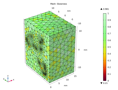
In the Expression text field, type x>1[mm] to visualize elements with at least one vertex with x-coordinate higher than 1 mm.
|
|
5
|
|
1
|
|
3
|
|
1
|
|
2
|
|
3
|
|
1
|
|
2
|
|
3
|
|
4
|
|
5
|
|
6
|
|
1
|
|
2
|
|
3
|
|
4
|
In the Mesh Plot 1 toolbar, click
|
|
1
|
|
2
|
|
3
|
|
1
|
|
3
|
|
4
|
|
5
|