|
|
The rest of the theory for the rack and pinion node is similar to the Theory for Gear Pairs with the following changes.
|
|
|
For more details, refer the Gear Pair Compatibility Criteria for the gear pair node.
|


|
|
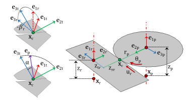
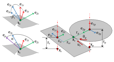
For more details, refer the Gear Local Coordinate System for the gear pair node.
|
|
|
For more details, refer the Contact Point Position and Offset for the gear pair node.
|
|
|
For more details, refer the Gear Pair Constraints for the gear pair node.
|