Theory for Gear Pairs
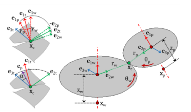
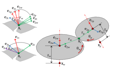
The Gear Pair node connects two spur gears, helical gears, or bevel gears in such a way that at the contact point, they have no relative motion along the line of action. The remaining displacements and rotations of both gears are independent of each other.
In case of a line contact model, one additional constraint is added to restrict the relative rotation about a line joining the two gear centers. When friction is included for a gear pair, frictional forces in the plane perpendicular to the line of action are added on both the gears.
Figure 3-11: Sketch of a gear pair where the line of action is computed by the clockwise rotation of the tangent.
The degrees of freedom at the gear pair are θwh and θpn. They are defined as the rotation of the wheel and pinion about the first axis of their respective local coordinate system.
Figure 3-12: Sketch of a gear pair where the line of action is computed by the counterclockwise rotation of the tangent.
The rest of this section discusses the following topics:
Gear Pair Compatibility Criteria
In a Gear Pair node, you can select any two gears defined for the model. However, for the correct tooth meshing, a set of gears must fulfill the compatibility criteria.
Normal Module
The normal module of both gears must be the same.
Pressure Angle
The pressure angle of both gears must be the same.
Configuration
For parallel axis helical gears, the sum of the helix angles must be zero.
For crossed axis helical gears, the sum of the helix angle must be nonzero.
Gear Local Coordinate System
The local coordinate system for each gear is created using the gear axis and the center of rotation of both gears. This local coordinate system is attached to the gear; however, it does not rotate with the gear local rotation.
Initial Local Coordinate System
The first axis for the wheel () and pinion () is an input on the respective nodes. In 2D, it is assumed to be the out-of-plane direction.
For a parallel or intersecting configuration, the second axis is defined as:
where xc,wh and xc,pn are the center of rotation of the wheel and pinion, respectively.
For a configuration that is neither parallel nor intersecting, the second axis is defined as:
In 2D:
The third axis is defined as follows:
Local Coordinate System
The first axis is defined as follows:
The second axis is defined as follows:
The third axis is defined as follows:
where Rwh and Rpn are the rotation matrices of the wheel and the pinion, respectively. The angles θwh and θpn are the rotations of the wheel and pinion about the first axis of their respective local coordinate system.
Gear Tooth Coordinate System
The gear tooth coordinate system is defined by rotating the gear local coordinate system with the helix angle and cone angle.
where Twh and Tpn are the tooth transformation matrix for the wheel and pinion, respectively.
The gear-to-tooth transformation matrix is defined as:
For the pinion tooth coordinate system, the sign of the second axis (e2t,pn) and third axis (e3t,pn) are reversed to match the directions with the wheel tooth coordinate system.
Line of Action
The line of action is the normal direction of the gear tooth surface at the contact point on the pitch circle. This is the direction along which the motion is transferred from one gear to another gear. It is defined by rotating the third axis of the tooth coordinate system (e3t) about the first axis of the tooth coordinate system (e1t) with the pressure angle (α).
The line of action, also known as the pressure angle direction, is defined as follows:
For clockwise rotation of the third axis:
For counterclockwise rotation of the third axis:
Gear Ratio
The gear ratio (gr) of a gear pair is defined as the ratio of angular velocities of the wheel (ωwh) and the pinion (ωpn):
It can also be written as the ratio of number of teeth of the pinion (npn) and the wheel (nwh):
Contact Point Position and Offset
Contact Point Position
The point of contact (xcp) on a gear in its local coordinate system can be defined as:
where, for the wheel and pinion, respectively:
xcp,wh and xcp,pn are the positions of the contact points
xc,wh and xc,pn are the centers of rotation
uwh and upn are the displacement vectors at the center of rotation
zwh and zpn are the contact point offsets from the center of rotation in the axial direction
rwh and rpn are the pitch radii
γwh and γpn are the cone angles
In 2D, the expressions for the position of contact points reduce to:
Contact Point Offset
The contact point offset from the wheel or pinion center of rotation in the axial direction is defined as follows:
For a parallel or intersecting configuration, the contact point offset from the pinion center (zpn) is the input. The contact point offset from the wheel center (zwh) is defined as:
For a configuration that is neither parallel nor intersecting, the contact point offset from the pinion center (zpn) and the contact point offset from the wheel center (zwh) are defined as:
where
Gear Pair Constraints
Rotation Constraint
This constraint relates the pinion rotation to the wheel rotation:
where θel, θet, and θbl are the transmission error (elasticity), transmission error (static), and transmission error (backlash), respectively.
By default, there is no elasticity, transmission error, or backlash in a gear pair hence all these transmission errors are zero.
Point Contact Constraint
At the contact point, the relative motion along the line of action must be zero. This can be written as:
Line Contact Constraint
In case of a line contact model, an additional constraint is added at the second contact point. This can be written as:
where xcp2,wh and xcp2,pn are the position of the second contact point and can be defined as:
Here, wpn and θcl are the working width of the pinion and the relative rotation about the centerline, respectively. By default, there is no elasticity on a gear pair; hence, the relative rotation about the centerline is zero.
Unique Triad Constraint
In case of planetary gears, there is a constraint to ensure that the local coordinate system of both the gears are still unique and well defined. This can be written as:
Contact Forces and Moments
Contact Force
When you compute a contact force using weak constraints, the point contact constraint is implemented in the weak form and the corresponding Lagrange multiplier gives the contact force (Fc).
Similarly, when you compute a contact force using a penalty method, the point contact constraint is implemented using the penalty factor and the corresponding penalty force gives the contact force (Fc).
For the case of a line contact model, the second contact force (Fc2) is computed by implementing the line contact constraint in the weak form or by using the penalty factor.
Contact Moment
When you compute a contact force using weak constraints, the unique triad constraint is implemented in the weak form and the corresponding Lagrange multiplier gives the moment at the contact point (Mc).
Similarly, when you compute a contact force computation using a penalty method, the unique triad constraint is implemented using the penalty factor and the corresponding penalty moment gives the moment at the contact point (Mc).
Force and Moment at Gear Centers
The forces at the gear centers are defined as:
The moments at the gear centers are defined as:
For a line contact model, additional contributions from the contact force Fc2 are added to the forces and moments at the gear centers. These contributions can be defined as: