Theory for Gear Elasticity
The Gear Elasticity node can optionally be added on gear pairs. In this node, you can specify the elastic properties of the gear mesh, such as mesh stiffness, mesh damping, and contact ratio. By default, the gear mesh is assumed rigid.
Figure 3-17: A sketch of a pair of teeth, showing the point of contact and the direction in which mesh stiffness and damping are interpreted.
The rest of this section discusses the following topics:
Degrees of Freedom
In this node, the transmission error (elasticity), θel, is a degree of freedom. This transmission error is added in the rotation constraint of the gear pair.
In the case of a line contact model, one more degree of freedom, θcl, is added. This is the relative rotation about the line joining the centers of two gears. The contribution of this rotation is added in the line contact constraint of the gear pair.
Elastic Moments
The elastic moment about the first axis of the tooth coordinate system and its virtual work contribution are defined as:
In the case of a line contact model, the elastic moment about the second axis of the tooth coordinate system and its virtual work contribution are defined as:
where
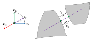
kg is the mesh stiffness of gear pair
cg is the mesh damping of gear pair
rpn is the pitch radius of pinion
wpn is the working width of pinion
Mesh Stiffness
To get equations that are specific to the Worm and Wheel node, replace “wheel” with “worm” and “pinion” with “wheel” everywhere.
To get equations that are specific to the Rack and Pinion node, replace “wheel” with “rack” everywhere.
Tooth Stiffness of Individual Gears
The mesh stiffness of the gear pair is defined as:
where kwh and kpn are the mesh stiffness of the wheel and pinion, respectively.
The mesh stiffness of the wheel, for different contact ratios, is defined as follows.
Contact ratio is constant and set to 1:
Figure 3-18: The graph shows the variation of the gear tooth stiffness in a mesh cycle.
The mesh stiffness of the wheel is defined as:
where
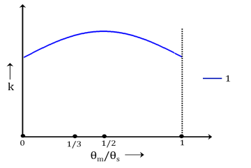
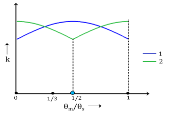
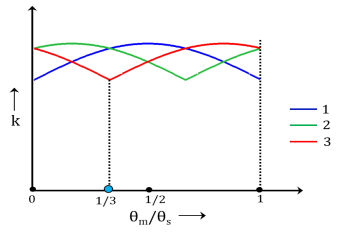
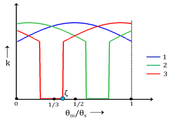
kt,wh is the gear tooth stiffness as function of mesh cycle
θm,wh is the mesh cycle
The mesh cycle for the wheel is defined as:
Contact ratio is constant and set to 2:
Figure 3-19: The graph shows the variation of the gear tooth stiffness of the first and second teeth in a mesh cycle.
The mesh stiffness of the wheel is defined as:
where kt2,wh is the tooth stiffness of the second tooth. It is defined as:
Contact ratio is constant and set to 3:
Figure 3-20: The graph shows the variation of the gear tooth stiffness of the first, second, and third teeth in a mesh cycle.
The mesh stiffness of the wheel is defined as:
where kt2,wh and kt3,wh are the tooth stiffness of the second and third teeth. respectively. They are defined as:
Contact ratio is varying and maximum contact ratio is set to 2:
Figure 3-21: The graph shows the variation of the gear tooth stiffness of the first and second teeth in a mesh cycle.
The mesh stiffness of the wheel is defined as:
where kt2f,wh and kt2b,pn are the tooth stiffness of the second forward and backward teeth. They are defined as:
where ζ is the next tooth engagement position in the mesh cycle. The value of ζ must be in the following range:
Contact ratio is varying and maximum contact ratio is set to 3:
Figure 3-22: The graph shows the variation of the gear tooth stiffness of the first, second, and third teeth in a mesh cycle.
The mesh stiffness of the wheel is defined as:
where
kt2f,wh and kt2b,pn are the tooth stiffness of the second forward and backward teeth
kt3f,wh and kt3b,pn are the tooth stiffness of the third forward and backward teeth
The value of ζ must be in the following range:
Total Stiffness of Gear Pair
The mesh stiffness of gear pair is defined as follows:
Function of wheel mesh cycle:
Function of wheel full revolution:
Function of pinion mesh cycle:
Function of pinion full revolution:
Mesh Damping
The mesh damping of a gear pair can be a constant value or it can be written as a function of mesh cycle or mesh stiffness.