Chain Drive
About Chain Drive
Transmission systems are devices used for transferring power from one place to another. A chain drive is an example of such transmission device that is widely used for various industrial applications. A typical chain drive is an assembly of two or more sprockets with a chain wrapped around them. Like gears, chain drives also transfer mechanical power from one shaft to another, however, they are more useful when the two shafts are placed at a distance from each other.
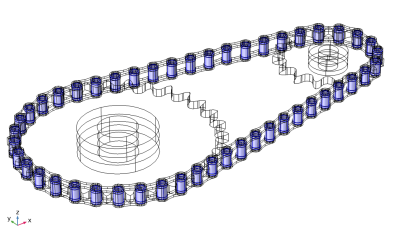
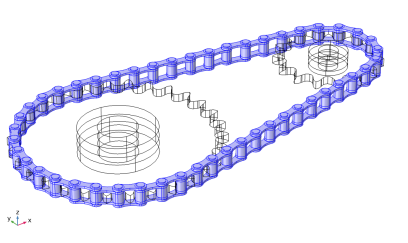
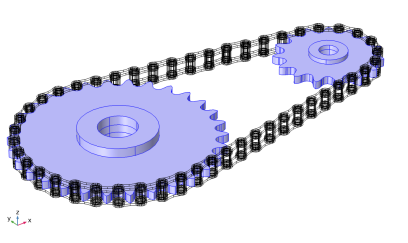
Using the Chain Drive node in the Multibody Dynamics interface, you can model a roller chain sprocket assembly in 2D or 3D. The Chain Drive node determines the interaction of the chain drive assembly, and automatically generates a set of physics nodes that are used to describe its behavior.
This section includes the following topics:
Geometry Settings
The Chain Drive node automatically creates a set of physics nodes in the Multibody Dynamics interface. This requires a geometry of the chain drive systems and a set of appropriate domain and boundary selections. With the Multibody Dynamics Module Part Library, you can either import a complete roller chain sprocket assembly, or create your own assembly from individual chain links and sprockets. Geometry parts are available in both 3D and 2D. The selections required to set up the physics of the chain drive system are predefined in the built-in geometry parts.
See the Chain Geometries section for details about various built-in geometries available in the Multibody Dynamics Module Part Library.
You can also create or import your own geometries, however, then you need to make sure that the final geometry is in the assembly state. Furthermore, you also need to create all selections required to set up the physics of the chain drive system manually.
Selection Settings
For a selected geometry part, the Chain Drive node automatically creates a set of physics nodes such as Rigid Material, Attachment, Hinge Joint, and Contact. These physics nodes are used for modeling the chain drive system. Creation of these physics nodes is based on a set of domain and boundary selections on the selected geometry.
There are several selection inputs required by the Chain Drive node. If the geometry of your chain drive system is built using the Multibody Dynamics Module Part Library, the Chain Drive node automatically selects proper domain and boundary selections from the geometry part.
See the Chain Geometries section for more details about the selections available for different geometry parts.
When using the built-in parts, you do not need to give any additional selection inputs. However, if you are using your own geometry, you need to input proper domain and boundary selections for each of the selection inputs as described below:
All the above selection inputs may not always be available. Depending on the type of modeling and other input parameters, some selection inputs may not be required. Selection inputs that are not required are hidden in the settings window of the Chain Drive node. For example, if you choose not to model the elastic bushings in a chain link, the Domain Selection, Bushing selection input does not appear in the Chain Drive node. Details about each of these selection inputs are given below.
Domain Selection, Link
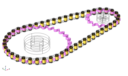
This is a domain selection input used to create a Rigid Material node on each link plate of the chain. If you use a geometry from the Multibody Dynamics Module Part Library, a built-in domain selection named Links is automatically selected. If you are using your own geometry, you need to input a domain selection containing all link plates. This selection input is available only when the chain links are modeled as rigid bodies.
Figure 2-17: Selection of all the link plates used for creating Rigid Material nodes.
Domain Selection, Sprocket
This is a domain selection input used to create a Rigid Material node on each sprocket. If you use a geometry from the Multibody Dynamics Module Part Library, a built-in domain selection named Sprockets is automatically selected. If you are using your own geometry, you need to input a domain selection containing both sprockets domains. This selection input is available only when the sprockets are modeled as rigid bodies.
Figure 2-18: Selection of both sprockets used for creating Rigid Material nodes.
Domain Selection, Bushing
If you choose to model the chain links as rigid bodies with elastic bushings inside, this selection input is required. The input needed here is a domain selection containing all bushing domains. Using this input, the Chain Drive node automatically creates a Linear Elastic Material node on all bushing domains. If you use a geometry from the Multibody Dynamics Module Part Library, a built-in domain selection named Bushings is automatically selected. If you are using your own geometry, you need to input a domain selection containing all bushings domains. This selection input is available only when the chain links are modeled as rigid bodies with elastic bushings.
Figure 2-19: Selection of bushing domains used for creating Linear Elastic Material node.
Boundary Selection, Pin
This input is a boundary selection used to create Attachment nodes on each pin plate of the chain. For 3D models created using the Multibody Dynamics Module Part Library, a built-in boundary selection named Pin Outer Boundaries is automatically selected. If you use your own geometry, you need to input a boundary selection containing the outer cylindrical surfaces of all pin plates.
For 2D models created from the Multibody Dynamics Module Part Library, a selection named Pin Inner Boundaries is automatically selected. If you use your own geometry, you need to input a boundary selection containing the inner boundaries of all pin plates.
Boundary Selection, Roller Inner
This input is a boundary selection used to create Attachment nodes on each roller plate of the chain. For models built using a geometry from the Multibody Dynamics Module Part Library, a built-in boundary selection named Roller Inner Boundaries is automatically selected. If you use your own geometry, you need to input a boundary selection containing the inner cylindrical surfaces of all roller plates.
Attachments created on the pin and roller plates having the same locations are used as the source and destination for hinge joints between them.
Figure 2-20: Selection on pin plate boundaries used for creating Attachment nodes. The roller inner boundaries selection is also at the same geometrical position.
Boundary Selection, Roller Outer
This input is a boundary selection used to model contact between the chain and the outer boundaries of the sprockets. If the contact method is mesh based, this selection is used for creating a Contact Pair between the roller plates and the sprockets. For models built using a geometry from the Multibody Dynamics Module Part Library, a built-in boundary selection named Roller Outer Boundaries is automatically selected. If you use your own geometry, you need to input a boundary selection containing the outer cylindrical surfaces of all roller plates.
Boundary Selection, Sprocket Outer
This boundary selection input is used to model contact between the chain and the outer boundaries of the sprockets. If the contact method is mesh based, this selection is used for creating a Contact Pair between the roller plates and the sprockets. For models built using a geometry from the Multibody Dynamics Module Part Library, a built-in boundary selection named Sprocket Outer Boundaries is automatically selected. If you use your own geometry, you need to input a boundary selection containing the outer surfaces of the sprockets.
Figure 2-21: Contact Pair between the outer boundaries of the roller and the outer boundaries of the sprockets.
Boundary selection, Sprocket Inner
This boundary selection input is used to create an Attachment and a Hinge Joint on each sprocket. These can be used to model the mounting the chain drive system to external components such as shafts. For models built using a geometry from the Multibody Dynamics Module Part Library, a built-in boundary selection named Sprocket Inner Boundaries is automatically selected. If you use your own geometry, you need to input a boundary selection containing the inner surfaces of both sprockets.
Figure 2-22: Selection of inner boundaries of the sprocket used for creating Attachment and Hinge Joint nodes.
Chain and Sprocket Types
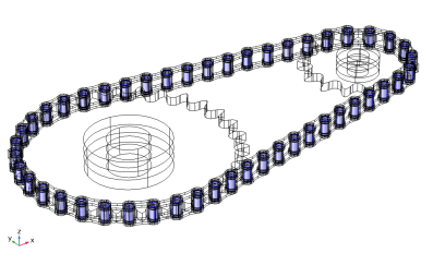
Using Chain Drive node, you can either model the chain links as rigid or elastic bodies. If the link plates are assumed rigid, the Chain Drive node automatically creates a Rigid Material node for each link plate, see Domain Selection, Link. It is also possible to model a chain with elastic bushings present between rigid link plates, see Domain Selection, Bushing.
The sprockets can also either be modeled as rigid or elastic bodies. If the sprockets are assumed rigid, the Chain Drive node automatically creates a Rigid Material node for each sprocket, see Domain Selection, Sprocket
Contact Method
The contact condition between the chain links and outer boundaries of the sprockets can be modeled with two different methods:
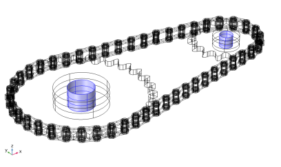
For the mesh-based contact method, the Chain Drive node automatically creates a contact pair between the outer boundaries of the rollers and the outer boundaries of the sprockets. A Contact node with penalty formulation is also added to the physics, which uses the created Contact Pair for computing the contact forces.
When the roller plates are assumed to be rigid, the roller center-based contact method can be used. From the center of each roller cylinder, the closest point on the outer boundary of the sprocket is determined using a general extrusion operator. The gap distance is defined as the distance between the outer boundary of the roller and its closest point on the sprocket in the direction of the spatial normal. This method is a penalty-based formulation, where the contact force is applied if the gap between a roller and the sprocket is negative. The input penalty factor determines the stiffness of the spring preventing penetration of the contacting bodies.
The mesh-based method is the most accurate of the two methods. It is, however, computationally expensive and only available when at least one of the two contacting bodies is assumed to be elastic. On the other hand, the roller center-based method is faster, but only available if the roller plates are assumed rigid.
Joint Settings
The Chain Drive node automatically generates a Hinge Joint node between each roller and pin plate. The axis of the Hinge Joints is the same as the sprocket axis. If you use a geometry form the Multibody Dynamics Module Part Library, the sprocket axis is automatically taken from the geometry part. It is also possible to change the axis of the sprocket, either by specifying a direction, or by selecting an edge parallel to the sprocket axis.
The Attachment nodes created on the roller and pin plates having same geometrical positions are used as the source and destination for the corresponding Hinge Joint. These attachments can either be rigid or flexible, depending on the setting in the parent Chain Drive node.
By default, the joints are assumed rigid, and the source and destination attachments are then rigidly connected in the directions in which the relative motion is restricted. However, it is possible to insert an elastic connection between attachment surfaces by setting Joint Type to Elastic in the Chain Drive node. This automatically sets all Hinge Joint nodes to be elastic. From the Chain Drive node, you can also control the viscous damping properties of each Hinge Joint in order to model losses, by activating rotational damping and setting a value for the damping coefficient c.
In most applications, the chain drive system is mounted some external component, such as shafts. Including the mounting is automated in the Chain Drive node, and you can select a check box to automatically create an Attachment node and a Hinge Joint node for each sprocket.
Create Links and Joints Button
The Creates Link and Joints Button is used to generate all physics nodes required to model the roller chain sprocket assembly. Keep the following points in mind when using this button:
Only click the Create Links and Joints button after setting appropriate values for all parameters in the Chain Drive node.
If you change one or more parameters in the Chain Drive node after the automatic creation of physics nodes, the settings of the associated physics nodes also require updates. Click the Create Links and Joints button again in order to update the settings of the existing physics nodes. A warning message is added under the Chain Drive node to notify when such an update is required.
If any selections or related parameters in the Chain Drive node are modified after the automatic creation of physics nodes, all associated physics nodes needs to be recreated. Click the Create Links and Joints button again in order to do this. Since all physics nodes are deleted and created again during this operation, the update may take a while. A warning message is added under the Chain Drive node to notify when such an update is required.