Defining Load Groups and Constraint Groups
For boundary conditions that represent loads and constraints, as well as other loads and constraints such as body loads, you can define load groups and constraint groups, which contain the loads and constraints, respectively, that you want to use as parts of load cases. All loads and constraints for structural mechanics as well as boundary conditions such as heat flux (a load) and temperature (a constraint) in heat transfer support load groups and constraint groups. You can create load groups and constraint groups in two ways: from the Global Definitions node’s context menu or a physics node’s context menu. Both methods add the node under Global Definitions.
Add a Load or Constraint Group from the Global Definitions Context Menu
Add a Load Group () or Constraint Group () under 
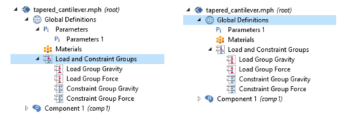
Global Definitions to create groups to which you can later assign loads and constraints. If you group the nodes, the load and constraint groups display under the Load and Constraint Groups node (). See Figure 3-22.
Figure 3-22: An example of the node grouping when Group by Type is selected (left) and when Ungroup is selected (right).
Add a Load or Constraint Group from a Physics Node Context Menu
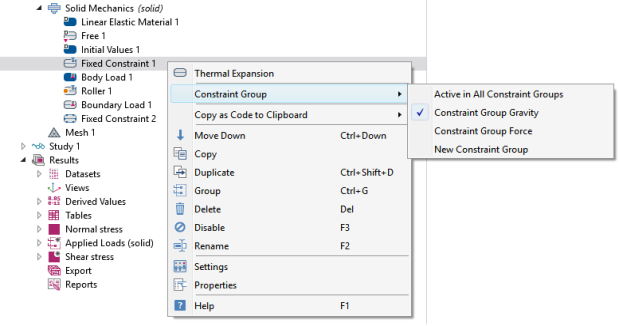
Right-click a physics node for any load or constraint (for example, a Fixed Constraint, Heat Source, or Boundary Load node) and choose Load Group>New Load Group or Constraint Group>New Constraint Group, respectively. The software creates a Load Group or Constraint Group under Global Definitions and at the same time assigns that physics node (a load or a constraint) to that group.
Assign a Load or Constraint to a Group
To assign a load or a constraint to a load group or constraint group, right-click the physics node for a load or constraint and from the Load Group or Constraint Group submenu choose one of the following (see Figure 3-23):
Active in All Load Groups (or Active in All Constraint Groups). This is the default setting, which you can use for some boundary conditions or other parts of the physics design that take part in all load cases.
New Load Group (or New Constraint Group) to create a new group as described earlier in this section.
Figure 3-23: An example of the context menu options when a load or constraint physics node is right-clicked, in this case, the Fixed Constraint node.
Define as many groups as you need for the load cases that you want to study. Each load or constraint can only belong to one group. The next step is then to define the actual load cases as combinations of these groups (see Defining and Evaluating Load Cases).
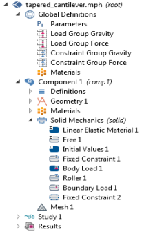
When the Load Group or Constraint Group is applied to a node under a physics interface, the node indicates this visually. For example, the Fixed Constraint and Roller nodes have the blue Constraint Group symbol in the upper-right corner and the Body Load and Boundary Load nodes have the red Load Group symbol in the upper-right corner as in Figure 3-24.
Figure 3-24: An example of the Load and Constraint Groups defined under Global Definitions with loads and constraints applied to nodes under Solid Mechanics.
Tapered Cantilever with Two Load Cases: Application Library path COMSOL_Multiphysics/Structural_Mechanics/tapered_cantilever
If you have the Structural Mechanics Module, also see Pratt Truss Bridge: Application Library path Structural_Mechanics_Module/Beams_and_Shells/pratt_truss_bridge.