In the Layered Material Stack node (

), you can compose a new layered material by stacking other layered materials (including Material nodes that define single-layer materials) on top of each other. There are three main reasons why you may want to do this:
The Layered Material Stack node is located in the Layers submenu under a Materials node. To compose the stack, you add subnodes to the
Layered Material Stack. These subnodes can be either a
Layered Material or a
Layered Material Link (Subnode). You can add any number of subnodes, and mix the two types. The order of the subnodes determines the ordering of the layers in the final laminate.
From the Transform list, choose one of the following options:
Select the Scale check box to scale the layered material’s thickness with a factor (default: 1). If you have defined a layer with a scaling factor, it appears in the preview window with a darker color than a nonscaled layer.
Click the Layer Cross Section Preview button (

to plot a preview of the layer cross section including the transformation. You can also click the downward pointing arrow to choose
Layer Cross Section Preview (

) or
Create Layer Cross Section Preview (

), which adds the preview plot as a new plot group under
Results. Click the
Layer Stack Preview button (

) to get a preview of the stack with the transformation. Click the
Create Layer Stack Plot button (

) to add the preview of the layer stack as a new plot group under
Results.
Select a Coordinate system defining the principal directions of the laminate. The orientation of each layer, given in the
Layered Material node, is a rotation from the first coordinate axis of this coordinate system. Only
Boundary System coordinate systems can be selected.
Choose a Position —
Midplane on boundary,
Down side on boundary,
Up side on boundary, or
User defined. This controls the possible offset of the layered material from the geometrical boundary on which the mesh exists (the
reference surface). For
User defined, enter a value for the
Relative midplane offset. The value
1 corresponds to
Down side on boundary, and the value
−1 corresponds to
Up side on boundary. Values may be outside the range
−1 to 1, in which case the reference surface is outside the laminate. If you use ply modeling, these additional positions are available:
Midplane of stack member on boundary,
Downside of stack member on boundary,
Upside of stack member on boundary. If you choose one of those positions, also choose a member of the ply stack from the
Stack member list. Also, with one of those positions, the
Automatic alignment when the selected stack member is not available check box is selected by default. The stack members (in zones that do not have the selected stack member) will then be aligned with the stack members in the zone that have the selected stack member. Clear it if you do not want that automatic alignment.
The Position setting is only used by physics features where the physical behavior depends of the actual location, such as structural shells.
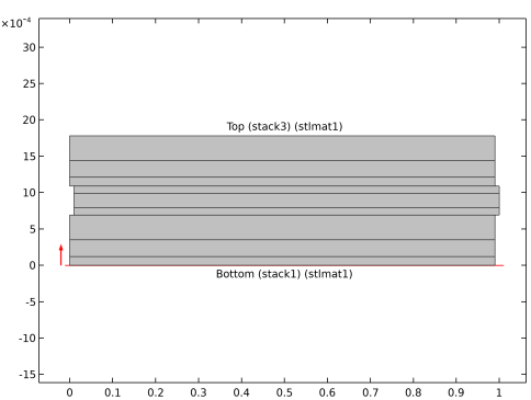
By clicking the Layer Cross Section Preview (

) button, you get a preview plot of the stacked layered material, including the location of the reference surface. In
Figure 9-13, a laminate composed of three stacked layered materials, each consisting of three layers is shown. Note that there is a slight indentation, used for emphasizing the transition from one part of the stack to the next.
You can also click the downward pointing arrow to choose Layer Cross Section Preview (

) or
Create Layer Cross Section Preview (

), which adds the preview plot as a new plot group under
Results.
By clicking the Go to Material (

) button, you can jump to the settings for the selected material.
Click the Add Material from Library button (

) to add a global material from the material libraries or a new blank global material. The added material then becomes the one selected in the
Material list.
The value of the Thickness-to-width ratio controls the height in the
y direction. The width is always unity.
Deselect the Shows labels in cross-section plot check box to remove the text labels showing layer names and materials.
The Value column will usually contain the string
Layer, indicating that the actual value is layer dependent.