The Layered Material Link node (

) provides a bridge from a
Layered Material, located under
Global Definitions, to a physics feature residing in a component. A physics feature designed to work with layered materials cannot directly reference a
Layered Material. The
Layered Material Link node is located in the
Layers submenu under a
Materials node.
By clicking the Go to Material (

) button, you can jump to the settings for the selected material.
Click the Add Layered Material button (

) to add another
Layered Material or a
Switch. The added material then becomes the one selected in the
Material list.
From the Transform list, choose one of the following options:
Select the Scale check box to scale the layered material’s thickness with a factor (default: 1).The scale can be a numerical value, a parameter, or an expression. Such an expression can, for example, be a function of the coordinates so that a surface with variable thickness can be described.
Click the Layer Cross Section Preview button (

to plot a preview of the layer cross section including the transformation (see the following plot for an example).
You can also click the downward pointing arrow to choose Layer Cross Section Preview (

) or
Create Layer Cross Section Preview (

), which adds the preview plot as a new plot group under
Results.
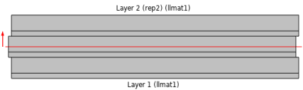
Click the Layer Stack Preview button (

) to get a preview of the stack with the transformation.
Select a Coordinate system defining the principal directions of the laminate. The orientation of each layer, given in the
Layered Material node, is a rotation from the first coordinate axis of this coordinate system. Only
Boundary System coordinate systems can be selected.
Choose a Position —
Midplane on boundary,
Down side on boundary,
Up side on boundary, or
User defined. This controls the possible offset of the layered material from the geometrical boundary on which the mesh exists (the
reference surface). For
User defined, enter a value for the
Relative midplane offset. The value
1 corresponds to
Down side on boundary, and the value
−1 corresponds to
Up side on boundary. Values can be outside the range
−1 to 1, in which case the reference surface is outside the laminate.
The Position setting is only used by physics features where the physical behavior depends of the actual location, such as structural shells.
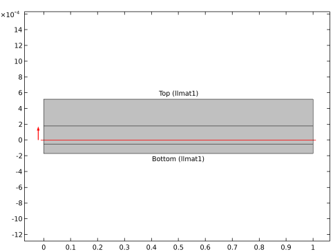
By clicking the Layer Cross Section Preview (

) button, you get a preview plot of the layered material, including the location of the reference surface (
Figure 9-12). The height of the laminate in the plot is controlled by the value of the
Thickness-to-width ratio specified in the
Preview Plot Settings for the selected layered material. You can also click the downward pointing arrow to choose
Layer Cross Section Preview (

) or
Create Layer Cross Section Preview (

), which adds the preview plot as a new plot group under
Results.
By clicking the Go to Material (

) button, you can jump to the settings for the selected material.
Click the Add Material from Library button (

) to add a global material from the material libraries or a new blank global material. The added material then becomes the one selected in the
Material list.
The value of the Thickness-to-width ratio controls the height in the
y direction. The width is always unity.
Deselect the Shows labels in cross-section plot check box to remove the text labels showing layer names and materials.
The Value column will usually contain the string
Layer, indicating that the actual value is layer dependent.