Ply-Based Modeling Approach
There are two ways in which a complex composite laminate, with different layups in different parts of the structure, can be modeled:
The zone-based modeling approach is a traditional way of defining a layup in a composite laminate. First, all zones in the composite laminate that have different layups are identified. Second, the layup in each zone is defined using the Layered Material Link or Layered Material Stack node. This approach works fine as long as there is a limited number of ply drop-offs, so that the number of zones is limited.
In the case of a complex composite laminate with many ply drop-offs, and thus many zones, identifying and then defining the layup for each zone individually becomes a cumbersome process. In such a scenario, a ply-based modeling approach can be used. Here, only one layup is defined for all the zones using a Layered Material Stack node. Each ply then has its own selection, which is a subset of the selection of the Layered Material Stack node. This is different compared to the zone- based modeling approach, where each ply in the Layered Material Stack has the same selection.
Figure 3-15: Zones created in the ply-based modeling approach. The layup in each zone can also be seen. A ply having sectioning represents the variable thickness ply.
Based on the overall layup information and the selection of each ply, different zones are automatically created and shown in the Stack Zone Definition section of the Layered Material Stack node. Each zone is treated as a different layered material and can be used accordingly in the physics and in postprocessing.
The typical steps involved in defining a complex layup using the ply-based modeling approach are:
Use a Layered Material Stack node and make the selection where you want to define a layup.
Add all the plies to the Layered Material Stack node in the specified stacking sequence using its subnodes — Layered Material link, Layered Material, or Single Layer Material.
The table in the Stack Zone Definition section lists the Name of the zones, the Stack members in each zone, and the geometric Selections of each zone.
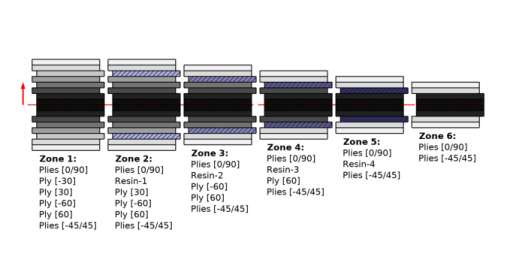
Click the Layer Cross Section Preview plot button to visualize all the zones and their stacking sequence, as shown in Figure 3-15.
Click the Layer Stack Preview plot button to visualize the overall stacking sequence, and further, click on each row of the table to visualize the stacking sequence in each zone.
In the COMSOL Multiphysics Reference Manual: Layered Material Stack