The next step is to define a coordinate system for the composite laminate in which the stacking sequence is interpreted. You can either customize the default Boundary System or add a new instances of boundary systems under the
Definitions node within a component. Select the coordinate system in the
Layered Material Link node.
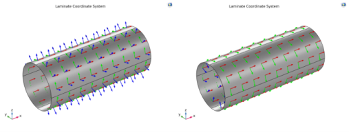
The first axis of the laminate coordinate system is aligned with the global x direction. This can be created by setting the
Create first tangent direction from option to
Global Cartesian (spatial) and
Axis to
x.
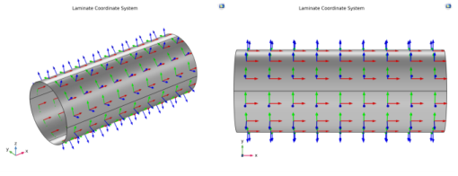
The first axis of the laminate coordinate system is at 45° to the global
x direction. This can be created by first defining a
Cylindrical System having
Longitudinal axis as
x-axis and then setting the
Create first tangent direction from to
Cylindrical System and
Axis to
Manual with
{0,-1,1} as orientation.
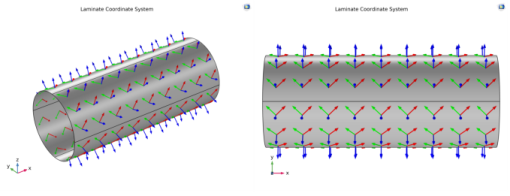
The first axis of laminate coordinate system is aligned with the global x direction but with the normal direction is pointing inward. This coordinate system can be created in a same way as in the first example. In addition to that, the
Reverse Normal direction option is selected in the
Boundary System node in order to point the normal vector inward.