
|
|
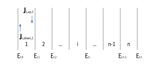
The Layered Transition Boundary Condition is based on the assumption that the wave propagates in the normal direction in the thin layer. Thus, the wave could be incident in the normal direction or the wave could be refracted to propagate in a direction close to the normal direction. The latter condition is fulfilled for a good conductor.
A consequence of the normal direction propagation assumption is that the Layered Transition Boundary Condition is not compatible with mode analysis, as for mode analysis it is assumed that the wave predominantly propagates in the out-of-plane direction whereas the normal to the boundary is in an in-plane direction.
|
|
•
|
In a Material node, the layer Thickness is set in the Material Contents section by adding a Shell property group from the Material Properties section in the material Settings window. This automatically adds a Shell subnode under the Material node, transforming it into a layered material.
|
|
•
|
When the layered material is a Single Layer Material, the Thickness is set in the Material Contents section in the Settings window. Alternatively it can be set in the Layer Definition section of the Shell property group Settings window.
|
|
•
|
For a general Layered Material, added through a Layered Material Link or a Layered Material Stack, the Thickness is set in the Layer Definition section of the Settings window. Several layers may be defined in the table, and the Thickness should be defined for each of them. The total thickness of the layered material is the sum of all the layers thicknesses.
|
|
•
|
|
•
|
|
•
|
Electrical conductivity, σ (SI unit: S/m)
|