The Heat Transfer Equation
This physics interface solves an energy balance equation for 1D pipes, taking the flow velocity as input.
Heat Balance Equation
The energy equation for an incompressible fluid flowing in a pipe is (Ref. 25):
(3-1)
where ρ is the fluid density (SI unit: kg/m3), A is the pipe cross section area (SI unit: m2) available for flow, Cp (SI unit: J/(kg·K)) is the heat capacity at constant pressure, T (SI unit: K) is the temperature. u is a velocity field. For information about the tangential velocity in pipe flow, see Theory for the Pipe Flow Interface. Further, k (SI unit: W/(m·K)) is the thermal conductivity. The second term on the right hand side corresponds to friction heat dissipated due to viscous shear. Q (SI unit: W/m) represents a general heat source and Qwall (SI unit: W/m) represents external heat exchange through the pipe wall. Note that the Qwall term is detailed below.
An additional term Qp can be added to the right-hand side of the equation by enabling the Pressure Work check box:
(3-2)
This term is optional and can be used if the pressure drop is expected to be considerable and the fluid is compressible. The contribution follows the same theory as the pressure work term described in the section The Nonisothermal Flow and Conjugate Heat Transfer Equations in the Heat Transfer Module User’s Guide.
Wall Heat Transfer
The radial heat transfer from the surroundings into the pipe is given by
(3-3) (W/m)
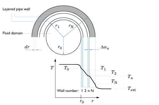
In Equation 3-3, (hZ)eff is an effective value of the heat transfer coefficient h (SI unit: W/(m2·K)) times the wall perimeter Z (SI unit: m) of the pipe. Text (SI unit: K) the external temperature outside of the pipe. See Figure 3-5. Qwall appears as a source term in the pipe heat transfer equation, Equation 3-1.
The Wall Heat Transfer feature requires the external temperature and at least an internal film resistance subnode added to it. The individual contributions of heat transfer coefficients can be added by subnodes to the Wall Heat Transfer feature. The subnodes are:
Text in Equation 3-3 can be a constant, parameter, expression, or given by a temperature field computed by another physics interface, typically a 3D Heat Transfer interface. h is automatically calculated through film resistances and wall layers that are added as subnodes; see Equation 3-17 an on.
If Text is given as the temperature field computed by another 3D Heat Transfer interface, automatic heat transfer coupling is done to the 3D physics side as a line source. The temperature coupling between the pipe and the surrounding domain is implemented as a line heat source in the 3D domain. The source strength is proportional to the temperature difference (Equation 3-3) between the pipe fluid and the surrounding domain.
The overall heat transfer coefficient including internal film resistance, wall resistance and external film resistance can be deduced as follows, with reference to Figure 3-5.
Figure 3-5: Temperature distribution across the pipe wall.
rn (SI unit: m) is the outer radius of wall n
w = r − r0 (SI unit: m) a wall coordinate, starting at the inner radius r0
Δwn = rn − rn1 (SI unit: m) the wall thickness of wall n
Zn (SI unit: m) is the outer perimeter of wall n
hint and hext are the film heat transfer coefficients on the inside and outside of the tube, respectively (SI unit: W/(m2·K)).
kn is the thermal conductivity (SI unit: W/(m·K)) of wall n
Shell balance
In Figure 3-5, consider a short length section ΔL of pipe, perpendicular to the figure plane. The heat leaving the internal fluid of that segment into the wall is
(3-4)(W)
Here, AQ =  ΔL2πr0 (SI unit: m2) is the area available for heat flux into the wall. For stationary conditions that same amount of heat must travel through any cylindrical shell at radius r in wall 1 (or any wall).
(3-5)
Rearrange and integrate from r0 to r1.
(3-6)
Perform the integration
(3-7)
and rearrange
(3-8).
For the example of two wall layers, the heat flow is equal across any shell from the inner bulk fluid to the surroundings, and we can set all .
(3-9)
Substituting
(3-10),
and making a linear combination of the equations Equation 3-9 gives
(3-11)
where (hAQ)eff is an effective conductance:
(3-12)
For the general case with N wall layers this reads
(3-13)
Now let
(3-14),
where Z (SI unit: m) is an average perimeter (circumference), of the pipe, taken over the thickness of the pipe walls. Combine Equation 3-10 and Equation 3-14 such a that
and insert in Equation 3-13:
(3-15)
For a circular pipe cross sections, this effective hZ in can now be used in Equation 3-3. Note the reversed sign since Qwall is the heat added to the pipe from the surroundings. The assumption in the deduction above is
For square and rectangular pipe shapes the average conductance can be approximated by the simpler sum of resistances across a plane wall, which can be found in for example (Ref. 14):
(3-16)
The film resistances can be calculated from
(3-17)
where k is the thermal conductivity of the material, and Nu is the Nusselt number. dh is the hydraulic diameter, defined as
(3-18).
The inner and outer film coefficients is evaluated at (T + T0)/2 and (TN + Text)/2, respectively.
The thermal conductivity kn can be temperature dependent and is evaluated at (Tn + Tn1)/2.
To compute dh in Equation 3-18 the local perimeter is calculated as Z = f(w) and the cross section area as A = f(w). Automatic calculations for circular tubes are done by the physics interface as Z = 2πr and A = πr2. For rectangular tubes it is Z = 2(width + height) and A = width · height. For user-defined pipe shapes, the user can enter arbitrary expressions.
The local temperatures in each radial position of the pipe wall (see Figure 3-5) are computed considering the fact that Equation 3-3 also can be applied for each individual wall layer:
(3-19)
Combining Equation 3-3, Equation 3-19 and Equation 3-15 or Equation 3-16 (depending on pipe shape) for each wall layer explicitly gives each Tn.
Internal Film Resistance
For internal laminar forced convection in fully developed pipe flow, the Nusselt number is a constant that depends on the pipe cross-section. Values are listed in the table below (Ref. 1). The Pipe Flow interface interpolates to find values for width/height ratios not listed. Default settings for film coefficient calculations are “Automatic”, which means that laminar and turbulent correlations are applied according to the Re number.
For user-defined cross sections, Nu is suggested to 3.66 as a default.
For internal turbulent forced convection (3000 < Re <  6·106, 0.5 < Pr <  2000), the Gnielinski equation (Ref. 19) applies:
(3-20)
Where Pr is the Prandtl number:
(3-21)
The film resistance due in the internal flow can be calculated using material properties defined in the Heat Transfer feature and the calculated friction factor. Material properties are evaluated at the mean internal film temperature (T + T0)/2 (see Expressions for the Darcy Friction Factor).
The using the hydraulic diameter makes the equations applicable to non-circular pipe cross sections.
External Film Resistance
The material properties used should be those of the external fluid. Do not set the material to Domain Material if you have a different fluid on the inside and outside. Typically, the temperature and pressure are required to evaluate the material functions. The external fluid velocity is required for the Forced Convection option and is a user-defined input.
For External forced convection around a pipe, valid for all Re and for Pr > 0.2, the Churchill and Bernstein (Ref. 20) correlation is used:
(3-22).
For External natural convection around a pipe, the Churchill and Chu (Ref. 21) correlation is used which is recommend for Ra < 1012:
(3-23)
where the Rayleigh number is given by:
(3-24)
and the Grashof number is:
(3-25)
Above d is the outside diameter of the pipe and, β is the fluid’s coefficient of volumetric thermal expansion:
(3-26)
Material properties are evaluated at (TN + Text)/2.
Stabilization of the Heat Transfer Equation
The transport equation in the Heat Transfer in Pipes interface is numerically stabilized.
Numerical Stabilization in the COMSOL Multiphysics Reference Manual