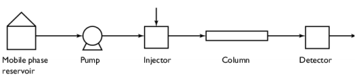
PDF

Liquid Chromatography
Introduction
Chromatography is an important group of methods to separate closely related components of complex mixtures. The following example simulates the separation of species in High Performance Liquid Chromatography (HPLC). In this technique an injector introduces a sample as a zone in a liquid mobile phase. The mobile phase containing the sample zone is pumped through a column containing a solid stationary phase; Figure 1 shows a diagram of such an instrument.
Figure 1: Diagram of an HPLC system.
The mobile and stationary phases are chosen so that the samples are distributed to varying degrees between the two phases. Those components that strongly adsorb to the stationary phase move only slowly with the flow of the mobile phase, and those that are weakly adsorbed move more rapidly. As the sample zones progress through the column, the components are separated into discrete zones that are recognized by a detector, situated beyond the outlet of the column.
Model Definition
This model studies the separation of two species under conditions of nonlinear chromatography in a 1D geometry. The Transport of Diluted Species in Porous Media interface is used, with convection and adsorption in porous media accounted for.
The equation for analyte transport through a chromatographic column, with constant porosity, is computed by:
(1)
Here, ci is the concentration of component i (SI unit: mol/m3), ε is the porosity, ρ is the density of the media within the column (for the mix of liquid and solid matrix, SI unit: kg/m3), kP,i is an adsorption isotherm, and u is the volume average velocity of the fluid phase (SI unit: m/s). The second term on the right-hand side describes the mixing of the solutes, including mechanical mixing (dispersion) and molecular diffusion. The two last terms on the right-hand side are a reaction rate term and a fluid source term.
Equation 1 comes from the following derivation:
First, consider the dispersion of the chromatographic zone to be negligible as it progresses through the column. The mass transport equation will then take the form:
where S denotes the specific surface area of the particles in the column (SI unit: m2/kg), ρp denotes the density of the solid particles (SI unit: kg/m3), ε equals the column porosity, A gives the inner area of the column tube, ni equals the analyte concentration in the stationary phase of component i (SI unit: mol/m2), v describes the mobile phase flow (SI unit: m3/s), and ci equals the analyte concentration in the mobile phase of component i (SI unit: mol/m3).
Equation 1 is defined according to the ideal model for chromatography that assumes that the equilibrium for the analyte between the mobile and stationary phases is immediate, that is:
where cP,i is the concentration of the component adsorbed to the solid (moles per dry unit).
The mass transport equation for the ideal chromatography model therefore becomes:
The dispersion or band broadening of the analyte zone is a result of a great number of random processes that the analyte experiences (for example, inhomogeneous flow and diffusion in pores and the mobile phase). It is therefore possible to formally express the band broadening as a diffusion process with an effective diffusion constant, Deff. Thus, Deff is a measure of the chromatographic system’s efficiency for a particular analyte. This constant is closely related to the concept of the height equivalent of a theoretical plate, H, that is customarily used in chromatographic practice. It can be shown that:
where vzi is the migration velocity of the analyte zone through the column. A mass balance that includes the zone-dispersion term gives the following equation:
Here Φ = Sρ( 1 − ε )/ε denotes the phase ratio of the column (SI unit: m2/m3), vl = v/(εA) gives the linear velocity of the mobile phase in the column (SI unit: m/s), and Deff is the effective diffusion constant (SI unit: m2/s).
This first example covers two components. The adsorption isotherm for both components is assumed to follow a Langmuir adsorption isotherm, that is,
and
where Ki is the adsorption constant for component i (SI unit: m3/mol), and n0i is the monolayer capacity of the stationary phase for component i (SI unit: mol/m2).
Using an effective zone-dispersion term and the kP,i adsorption isotherm notation gives Equation 1 without the reaction rate and a fluid source terms:
Input Data
This example looks at the progress of the chromatographic zone within the column. The physical data for the column correspond to a 12 cm-by-4 mm inner diameter column filled with 5 μm porous particles. The rest of the input data appear in Table 1.
Table 1: input data.
ρp
ε
vl
Deff1
110-8 m2/s
Deff2
110-8 m2/s
K1
0.04 m3/mol
K2
0.05 m3/mol
n01
110-6 mol/m2
n02
510-7 mol/m2
The injector concentrations for the two components are described by a normal distribution and are set up with the help of a Gaussian pulse function with an amplitude of 1 (Figure 2).
Figure 2: Injection pulse with amplitude 1.
The maximum inlet concentrations are 1 mol/m3 and 10 mol/m3 for components 1 and 2, respectively.
Results and Discussion
Figure 3 shows the mobile concentration zones of component 1 at various times. Initially, the concentration is zero in the column and at approximately 5 s the whole component mixture has been injected through the leftmost boundary (the inlet). At approximatively 385 s, the first trace of component 1 exits the rightmost boundary (the outlet). The zones are nearly symmetrical and normally distributed, indicating that the solution is affected by an almost linear adsorption isotherm.
Figure 3: The concentration of component 1 in the mobile phase at various times.
In Figure 4, the zones for both of the components are displayed at various times. For the present conditions a clear separation of the two components occurs within the column; the component zones do not overlap as they reach the outlet. As an example, at t=300 s, component 2 is no longer present in the mobile phase of the column, while most of component 1 still remains. Here, it is shown that component 2 depends on a nonlinear adsorption isotherm, quickly obtaining an asymmetrical mobile concentration zone (cf. Figure 2).
Figure 4: The concentrations of components 1 (solid) and 2 (dashed) in the mobile phase at various times.
The concentrations that are registered over time by the detector unit in the HPLC system are displayed in Figure 5. The first peak is that of component 1 and the second that of component 2.
Figure 5: Concentration at the outlet of the column, that is, the concentration monitored by the system detector.
References
1. D. DeVault, “The Theory of Chromatography,” J. Am. Chemical Soc., vol. 65, pp. 532–540, 1943.
2. S. Golshan-Shirazi and G. Guiochon, “Analytical solution for the ideal model of chromatography in the case of a Langmuir isotherm,” Analytical Chemistry, vol. 60, no. 21, pp. 2364–2374, 1988.
3. B. Lin and G. Guiochon, Modeling for Preparative Chromatography, Elsevier Publishing, Amsterdam, 2003.
Application Library path: Chemical_Reaction_Engineering_Module/Mixing_and_Separation/liquid_chromatography_1
Modeling Instructions
From the File menu, choose New.
New
In the New window, click  Model Wizard.
Model Wizard
1
In the Model Wizard window, click  1D.
2
In the Select Physics tree, select Chemical Species Transport>Transport of Diluted Species in Porous Media (tds).
3
Click Add.
4
In the Number of species text field, type 2.
5
Click  Study.
6
In the Select Study tree, select General Studies>Time Dependent.
7
Root
Add the model parameters from a text file.
Global Definitions
Parameters 1
1
In the Model Builder window, under Global Definitions click Parameters 1.
2
In the Settings window for Parameters, locate the Parameters section.
3
Click  Load from File.
4
The injection of the sample into the column is modeled with a Gaussian pulse.
Injection pulse
1
In the Home toolbar, click  Functions and choose Global>Gaussian Pulse.
2
In the Settings window for Gaussian Pulse, type Injection pulse in the Label text field.
3
In the Function name text field, type p1.
4
Locate the Parameters section. In the Location text field, type 3.
Variables 1
1
In the Model Builder window, right-click Global Definitions and choose Variables.
2
In the Settings window for Variables, locate the Variables section.
3
Geometry 1
Interval 1 (i1)
1
In the Model Builder window, under Component 1 (comp1) right-click Geometry 1 and choose Interval.
2
In the Settings window for Interval, locate the Interval section.
3
4
Click  Build All Objects.
5
Click the  Zoom Extents button in the Graphics toolbar.
Transport of Diluted Species in Porous Media (tds)
Porous Medium 1
In the Model Builder window, under Component 1 (comp1)>Transport of Diluted Species in Porous Media (tds) click Porous Medium 1.
Adsorption 1
1
In the Physics toolbar, click  Attributes and choose Adsorption.
2
In the Settings window for Adsorption, locate the Adsorption section.
3
Select the Species c1 check box.
4
Select the Species c2 check box.
5
Locate the Matrix Properties section. Find the Density subsection. From the ρ list, choose User defined. In the associated text field, type rho_c.
6
Locate the Adsorption section. In the KL,c1 text field, type K1.
7
In the cP,max,c1 text field, type S*n01.
8
In the KL,c2 text field, type K2.
9
In the cP,max,c2 text field, type S*n02.
Fluid 1
1
In the Model Builder window, expand the Porous Medium 1 node, then click Fluid 1.
2
In the Settings window for Fluid, locate the Convection section.
3
Specify the u vector as
4
Locate the Diffusion section. In the DF,c1 text field, type D_1.
5
In the DF,c2 text field, type D_2.
Porous Matrix 1
1
In the Model Builder window, click Porous Matrix 1.
2
In the Settings window for Porous Matrix, locate the Matrix Properties section.
3
From the εp list, choose User defined. In the associated text field, type eps_p.
Inflow 1
1
In the Physics toolbar, click  Boundaries and choose Inflow.
The investigated sample is injected at the leftmost boundary.
2
3
In the Settings window for Inflow, locate the Concentration section.
4
In the c0,c1 text field, type c01*pulse_inj.
5
In the c0,c2 text field, type c02*pulse_inj.
Outflow 1
1
In the Physics toolbar, click  Boundaries and choose Outflow.
2
Mesh 1
Edge 1
In the Mesh toolbar, click  Edge.
Size
1
In the Model Builder window, click Size.
2
In the Settings window for Size, locate the Element Size section.
3
Click the Custom button.
4
Locate the Element Size Parameters section. In the Maximum element size text field, type 1e-4.
5
Click  Build All.
Study 1
Step 1: Time Dependent
1
In the Model Builder window, under Study 1 click Step 1: Time Dependent.
2
In the Settings window for Time Dependent, locate the Study Settings section.
3
In the Output times text field, type range(0,1,420).
4
From the Tolerance list, choose User controlled.
5
In the Relative tolerance text field, type 0.0010.
Solution 1 (sol1)
1
In the Study toolbar, click  Show Default Solver.
2
In the Model Builder window, expand the Solution 1 (sol1) node.
3
In the Model Builder window, expand the Study 1>Solver Configurations>Solution 1 (sol1)>Dependent Variables 1 node, then click Concentration (comp1.c1).
4
In the Settings window for Field, locate the Scaling section.
5
From the Method list, choose Manual.
6
In the Scale text field, type c01.
7
In the Model Builder window, under Study 1>Solver Configurations>Solution 1 (sol1)>Dependent Variables 1 click Concentration (comp1.c2).
8
In the Settings window for Field, locate the Scaling section.
9
From the Method list, choose Manual.
10
In the Scale text field, type c02.
11
In the Model Builder window, under Study 1>Solver Configurations>Solution 1 (sol1) click Time-Dependent Solver 1.
12
In the Settings window for Time-Dependent Solver, click to expand the Absolute Tolerance section.
13
From the Tolerance method list, choose Manual.
14
In the Absolute tolerance text field, type 1e-4.
15
In the Study toolbar, click  Compute.
Results
Concentration, c1 (tds)
Follow these steps to reproduce the plot in Figure 3:
1
In the Model Builder window, under Results click Concentration, c1 (tds).
2
In the Settings window for 1D Plot Group, locate the Data section.
3
From the Time selection list, choose Interpolated.
4
In the Times (s) text field, type 5 50 100 200 300 385.
5
Click to expand the Title section. From the Title type list, choose None.
6
Locate the Plot Settings section. Select the x-axis label check box.
7
8
Locate the Axis section. Select the Manual axis limits check box.
9
In the y minimum text field, type 0.
Line Graph 1
1
In the Model Builder window, expand the Concentration, c1 (tds) node, then click Line Graph 1.
2
In the Settings window for Line Graph, click to expand the Coloring and Style section.
3
In the Width text field, type 2.
4
Click to expand the Legends section. Select the Show legends check box.
5
In the Concentration, c1 (tds) toolbar, click  Plot.
Follow these steps to reproduce the plot in Figure 4:
Concentrations, All Species (tds)
1
In the Model Builder window, under Results click Concentrations, All Species (tds).
2
In the Settings window for 1D Plot Group, locate the Data section.
3
From the Time selection list, choose Interpolated.
4
In the Times (s) text field, type 10 100 200 300.
5
Locate the Title section. From the Title type list, choose None.
Species c1
1
In the Model Builder window, expand the Concentrations, All Species (tds) node, then click Species c1.
2
In the Settings window for Line Graph, locate the Coloring and Style section.
3
In the Width text field, type 2.
4
Locate the Legends section. Find the Include subsection. Select the Solution check box.
5
Clear the Expression check box.
Species c2
1
In the Model Builder window, click Species c2.
2
In the Settings window for Line Graph, locate the Coloring and Style section.
3
Find the Line style subsection. From the Line list, choose Dashed.
4
From the Color list, choose Cycle (reset).
5
In the Width text field, type 2.
6
Locate the Legends section. Clear the Show legends check box.
Concentrations, All Species (tds)
1
In the Model Builder window, click Concentrations, All Species (tds).
2
In the Settings window for 1D Plot Group, locate the Plot Settings section.
3
Select the x-axis label check box.
4
5
Locate the Axis section. Select the Manual axis limits check box.
6
In the y minimum text field, type 0.
7
In the Concentrations, All Species (tds) toolbar, click  Plot.
Follow these steps to reproduce the plot in Figure 5:
Detected concentration
1
In the Home toolbar, click  Add Plot Group and choose 1D Plot Group.
2
In the Settings window for 1D Plot Group, type Detected concentration in the Label text field.
3
Locate the Title section. From the Title type list, choose None.
Point Graph 1
1
Right-click Detected concentration and choose Point Graph.
2
3
In the Settings window for Point Graph, locate the y-Axis Data section.
4
In the Expression text field, type c1+c2.
5
Click to expand the Coloring and Style section. In the Width text field, type 2.
Detected concentration
1
In the Model Builder window, click Detected concentration.
2
In the Settings window for 1D Plot Group, locate the Plot Settings section.
3
Select the y-axis label check box.
4
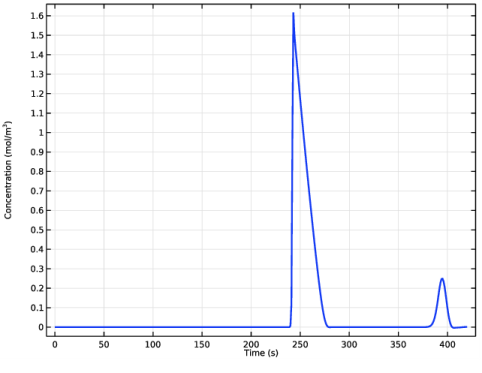
In the associated text field, type Concentration (mol/m<sup>3</sup>).
5
In the Detected concentration toolbar, click  Plot.
Concentrations, All Species (tds)
Last, an animation of the liquid chromatography process can be set up in the following manner:
Liquid chromatography animation
1
In the Results toolbar, click  Animation and choose File.
2
In the Settings window for Animation, type Liquid chromatography animation in the Label text field.
3
Locate the Scene section. From the Subject list, choose Concentrations, All Species (tds).
4
Locate the Target section. From the Target list, choose Player.
5
Locate the Animation Editing section. From the Time selection list, choose Interpolated.
6
Click  Range.
7
In the Range dialog box, type 0 in the Start text field.
8
In the Step text field, type 2.
9
In the Stop text field, type 420.
10
Click Replace.
11
Click the  Play button in the Graphics toolbar.