Directional Light
By default, a View contains three Directional Light () nodes. To add additional directional lights:
In the Model Builder under Definitions click View. In the View toolbar click Directional Light, or
Right-click the View node and select Directional Light.
It is also possible to convert an added a Headlight node to a Directional Light.
A directional light represents light that falls from a direction on all objects in the scene, like sunlight where all the light rays are parallel. Directional lights therefore have no position. You can adjust the direction of the light, the light and specular intensity levels, and the color as needed.
Figure 6-22 is an example of three Directional Light nodes where the color is changed and the light intensity adjusted for Directional Light 3. The markers are labeled 1, 2, and 3 to correspond to the nodes. The Directional Light 3 node’s light intensity setting is changed from 0.24 to 1 — the change in arrow size corresponds to the increase in light intensity. The wireframe around a light marker means that the corresponding node is selected in the Model Builder. Adjust the direction of the light, the light and specular intensity levels, and the color as needed.
Figure 6-22: Examples of directional light markers and the location of each directional light. The markers and light can be color coded to see which areas need adjustment. The markers indicate which node is selected in the Model Builder (a wireframe around the arrow in 2 and 3a), and the level of light intensity applied (the size of the arrow; compare 3 and 3a).
Direction
The x, y, and z coordinates define the direction in which the light falls on the objects in the scene. The arrow is a visualization of that direction with a placement that is calculated automatically depending of the scene’s bounding box. The arrow points in the direction of the light.
Settings
Adjust some of the settings such as the intensity and color of the directional light.
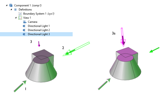
Enter a Light Intensity or use the slider to select values. Watch the changes in the Graphics window at the same time to help choose a level. When adjusting the light intensity, the light marker changes in length as the corresponding intensity is changed on the object.
Enter a Specular intensity (the intensity of the light that reflects off the surface of the geometry and used to define spheres and curves). This setting is turned ON and OFF on the View page (the default is ON), and the levels are adjusted for each Specular intensity using the field or the slider to select values between 0 and 1 (default value: 1). Watch the changes in the Graphics window at the same time to help choose a level. See Figure 6-20 for an example of specular light.
Select a Color: White (default), Custom, Black, Blue, Cyan, Green, Magenta, Red, or Yellow. If you select Custom, click the Color button to choose a color from the Custom color palette.
By default, the Lock to camera coordinate system check box is selected to make the light rotate together with the camera. Click to clear as needed; the light then follows the geometry.
By default, the Show light marker is selected. The light marker is associated to the type of light applied to the object. See Figure 6-21 for examples. Click to clear the check box as needed and remove the marker from the Graphics window.