About the 3D View Light Sources and Attributes
Light sources are the Directional Light, Point Light, Spotlight, or Headlight nodes. Light attributes are the scene light components, which include diffuse, specular, and ambient light (see Figure 6-20). Combined, these attribute and source settings enable the software to render the 3D model to look realistic.
Light Attributes
Figure 6-20: Scene light is a combination of ambient, diffuse, and specular light attributes. The default Scene light color is white and in this example the attributes display as different shades of black and gray. The Scene light is further enhanced using the various light source nodes.
Scene Light
For all geometry, scene light is applied by default and is a combination of the different light attributes. The light intensity and ambient intensity levels are also attributes of the scene light. The diffuse, specular, and ambient light attributes can be turned on or off by selecting or clearing the corresponding check boxes (see View (3D)). The intensity levels are adjusted either with a slider or by entering a number between 0 and 1.
Think of Scene light as ambient light, the base amount of light, plus specular light to add depth to curves and diffuse light to soften the lighting and add contrast. See Figure 6-20 for examples of the attributes:
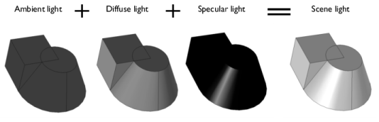
Ambient light is the available light surrounding the geometry. By itself, ambient light makes a 3D object look like a 2D object. The addition of diffuse and specular light adds the contrast and depth needed to define 3D geometry.
Diffuse light is directional and spreads out over the object, like a flashlight shining on a sphere. This generally adds contrast and depth of field to 3D objects.
Specular light is directional and reflects off the surface of a sphere or curve in a geometry. It is based on the angle between the viewer and the light source.
Apply the different sources of light (Directional Light, Point Light, Spotlight, or Headlight nodes) to further enhance how the geometry displays.
Light Sources
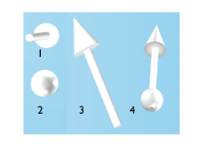
For 3D models, you can also add these light source nodes — Directional Light (), Point Light (), Spotlight (), and Headlight () — to adjust how the color and shading displays in the Graphics window. Each View can have a maximum of eight light sources (nodes) in any combination. See Directional Light, Point Light, Spotlight, and Headlight below.
Each light source has a unique light marker displayed in the Graphics window. Figure 6-22 shows three directional light settings and markers displayed in the Graphics window. The light markers are placed at the user-defined x, y, and z coordinates and are used to adjust the light and specular intensities on the object. You can show or hide the markers and change the color. The color of the marker corresponds to the light hitting the object. A wireframe around a light marker indicates that its node is selected in the Model Builder. When adjusting the light intensity, the light marker changes in length as the corresponding intensity is changed on the object. When adjusting the spread angle for a spotlight, the arrow increases and decreases in width as the angle value increases and decreases.
Figure 6-21: The light markers for each type of light source: (1) Headlight,(2) Point light, (3) Direction light, and (4) Spotlight.