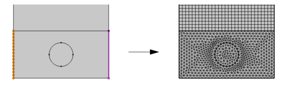
Add a Copy Edge node to 2D (

) and 3D (

) models to create identical meshes on edges. A 3D
Copy Edge feature can also be used for destination edges of different shapes.

Click the Active button to toggle between turning ON

and OFF

selections. Select the edges to copy the mesh from in the
Graphics window.
Click the Swap Source and Destination button (

) to switch source and destination selections. Edge map is available to be switched, if provided.
Select Automatic orientation to let the software determine the orientation of the source mesh on the destination automatically (this is the default), select
Same orientation to let the source mesh be copied to the destination according to the direction of the edges, and select
Opposite orientation to let the source mesh be copied to the destination in the opposite direction. Use the option
Show edge direction arrows in the
View node under the
Definitions node to view the arrow direction.
Select the Smooth across removed control entities check box to smooth the transition in element size across removed control entities. You can specify the number of smoothing iterations in the
Number of iterations field. In the
Maximum element depth to process field you can specify the maximum element depth for the mesh points to be smoothed.

