PDF

Directional Coupler
Introduction
Directional couplers are used for coupling a light wave from one waveguide to another waveguide. By controlling the refractive index in the two waveguides, for instance by heating or current injection, it is possible to control the amount of coupling between the waveguides.
Figure 1: Schematic drawing of the waveguide structure. The structure consists of the two waveguide cores and the surrounding cladding. Port 1 and 2 are used for exciting the waveguides and Port 3 and 4 absorb the waves.
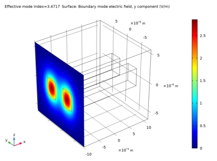
Light that propagates through a dielectric waveguide has most of the power concentrated within the central core of the waveguide. Outside the waveguide core, in the cladding, the electric field decays exponentially with the distance from the core. However, if you put another waveguide core close to the first waveguide (see Figure 1), that second waveguide perturbs the mode of the first waveguide (and vice versa). Thus, instead of having two modes with the same effective index, one localized in the first waveguide and the second mode in the second waveguide, the modes and their respective effective indices split and you get a symmetric supermode (see Figure 2 and Figure 4 below), with an effective index that is slightly larger than the effective index of the unperturbed waveguide mode, and an antisymmetric supermode (see Figure 3 and Figure 5), with an effective index that is slightly lower than the effective index of the unperturbed waveguide mode.
Since the supermodes are the solution to the wave equation, if you excite one of them, it propagates unperturbed through the waveguide. However, if you excite both the symmetric and the antisymmetric mode, that have different propagation constants, there is a beating between these two waves. Thus, you see that the power fluctuates back and forth between the two waveguides, as the waves propagate through the waveguide structure. You can adjust the length of the waveguide structure to get coupling from one waveguide to the other waveguide. By adjusting the phase difference between the fields of the two supermodes, you can decide which waveguide is initially excited.
Model Definition
The directional coupler, as shown in Figure 1, consists of two waveguide cores embedded in a cladding material. The cladding material is GaAs, with ion-implanted GaAs for the waveguide cores. The structure is modeled after Ref. 1.
The core cross-section is square, with a side length of 3 μm. The two waveguides are separated 3 μm. The length of the waveguide structure is 2 mm. Thus, given the tiny cross-section, compared to the length, it is advantageous to use a view that doesn’t preserve the aspect ratio for the geometry.
For this kind of problem, where the propagation length is much longer than the wavelength, the Electromagnetic Waves, Beam Envelopes interface is particularly suitable, as the mesh does not need to resolve the wave on a wavelength scale, but rather the beating between the two waves.
The model is setup to factor out the fast phase variation that occurs in synchronism with the first mode. Mathematically, write the total electric field as the sum of the electric fields of the two modes:
The expression within the square parentheses is solved for. It has a beat length L defined by
or
In the simulation, this beat length must be well resolved. Since the waveguide length is half of the beat length and the waveguide length is discretized into 20 subdivisions, the beat length is well resolved in the model.
The model uses two numeric ports per input and exit boundary (see Figure 1). The two ports define the lowest symmetric and antisymmetric modes of the waveguide structure.
In the second part of the modeling procedure, the bidirectional formulation is used. In this case, the two wave vectors are codirectional — they point in the same direction. However, the magnitude of the wave vectors are given by the propagation constants of the two beating modes. In this case, you expect the two waves to have almost constant amplitudes, so the mesh can be very coarse in the propagation direction.
A problem with the first two procedures is that the numerical procedure returns mode fields with an arbitrary phase. Thus, when you superpose the two input port modes, the result can be different on different computers. In the last part of the modeling procedure, it is shown how you can form a summation of the mode fields, with expansion coefficients that are calculated to minimize the difference between the summed mode fields and a target field. Thereby, independently of the mode fields’ phases, the resulting superposition will be stable.
The summation of the two input ports’ mode fields should approximate the target field, as expressed in
(1),
where ET,target is the tangential target electric field and ci and ET0,i are the expansion coefficients and the tangential non-normalized electric mode fields for mode i, respectively. Taking the cross product with the complex conjugate of the tangential magnetic mode field for mode j, multiplying with the port normal and integrating over the port boundary, we get
(2),
where Pj is the mode power for mode j. Thus, the expansion coefficients are given by the overlap integral
(3).
COMSOL defines the normalized mode field as
(4),
where Pin,i is the specified input power for mode i and θin,i is the corresponding specified mode phase.
Comparing Equation 1, Equation 3, and Equation 4, we can deduce that
(5)
or
(6)
and
(7).
Equation 6 and Equation 7 can now be used for specifying the input power and mode phase for the two exciting ports.
Results and Discussion
Figure 2 to Figure 5 shows the results of the initial boundary mode analysis. The first two modes (those with the largest effective mode index) are both symmetric. Figure 2 shows the first mode. This mode has the transverse polarization component along the z-direction. The second mode, shown in Figure 4, has transverse polarization along the y-direction.
Notice that your plots may look different from the plots below, as the plots show the real part of the boundary mode electric fields. The computed complex electric fields can have different phase factors than for the plots below. Thus, the color legends can have different scales and the fields can either show minima (a blue color) or maxima (a red color) at the locations for the waveguide cores. However, for a symmetric mode, it has the same field value for both waveguide cores and for an antisymmetric mode, it has opposite field values for the two waveguide cores.
Figure 2: The symmetric mode for z-polarization. Notice that the returned solution can also show the electric field as positive values in the peaks at the cores.
Figure 3: The antisymmetric mode for z-polarization.
Figure 3 and Figure 5 show the antisymmetric modes. Those have effective indexes that are slightly smaller than those of the symmetric modes. Figure 3 shows the mode for z-polarization and Figure 5 shows the mode for y-polarization.
Figure 4: The symmetric mode for y-polarization. Notice that the returned solution can also show the electric field as positive values in the peaks at the cores.
Figure 5: The antisymmetric mode for y-polarization.
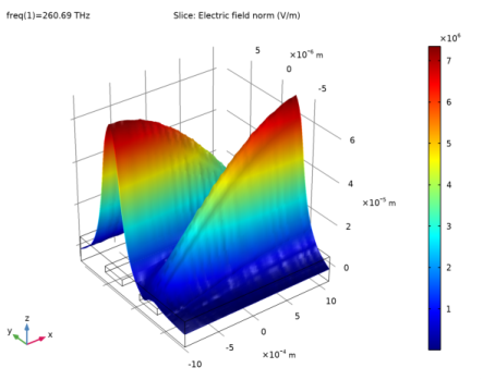
Figure 6 shows how the electric field increases in the receiving waveguide and decreases in the exciting waveguide. In a longer waveguide, the waves would oscillate back and forth between the waveguides.
Figure 6: Excitation of the symmetric and the antisymmetric modes. The wave couples from the input waveguide to the output waveguide. Notice your result may show that the wave is excited in the other waveguide core, if your mode fields have different signs than what is displayed in Figure 2 to Figure 5.
Figure 7 shows the result, when there is a π phase difference between the fields of the exciting ports. In this case, the superposition of the two modes results in excitation of the other waveguides (as compared to the case in Figure 6).
Figure 7: The same excitation conditions as in Figure 6, except that there is a phase difference between the two ports of π radians. Notice your result may show that the wave is excited in the other waveguide core, if your mode fields have different signs than what is displayed in Figure 2 to Figure 5.
Figure 8 and Figure 9 display the amplitudes of the first and second wave, respectively, when the bidirectional formulation is used. As expected, the amplitudes are almost constant.
Figure 8: The amplitude of the first wave, when the bidirectional formulation is used.
Figure 9: The amplitude of the second wave, when the bidirectional formulation is used.
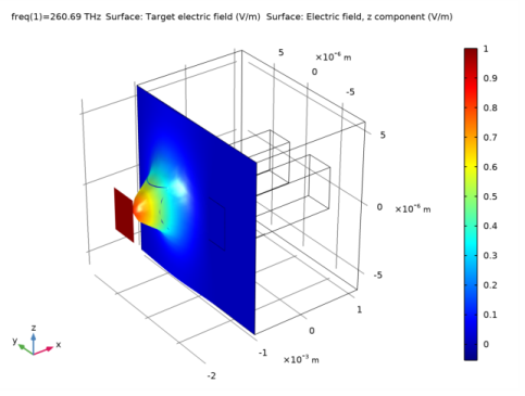
Figure 10 shows that the input field approximates the square target field, centered on the left waveguide, when the input power and the mode phase for the two exciting ports are calculated using an overlap integral between the target field and the mode field (c.f. Equation 6 and Equation 7).
Figure 10: The red square with amplitude 1 V/m represents the target function. This target function has an amplitude of1 V/m in the left waveguide core and 0 V/m everywhere else. The total input field is shown to be localized in the left waveguide, as expected, with an amplitude that approaches the target amplitude.
Reference
1. S. Somekh, E. Garmire, A. Yariv, H.L. Garvin, and R.G. Hunsperger, “Channel Optical Waveguides and Directional Couplers in GaAs-lmbedded and Ridged”, Applied Optics, vol. 13, no. 2, pp. 327–30, 1974.
Application Library path: Wave_Optics_Module/Waveguides_and_Couplers/directional_coupler
Modeling Instructions
From the File menu, choose New.
New
In the New window, click  Model Wizard.
Model Wizard
1
In the Model Wizard window, click  3D.
2
In the Select Physics tree, select Optics>Wave Optics>Electromagnetic Waves, Beam Envelopes (ewbe).
3
Click Add.
4
Click  Study.
5
In the Select Study tree, select Preset Studies for Selected Physics Interfaces>Boundary Mode Analysis.
6
Global Definitions
First, define a set of parameters for creating the geometry and defining the material parameters.
Parameters 1
1
In the Model Builder window, under Global Definitions click Parameters 1.
2
In the Settings window for Parameters, locate the Parameters section.
3
Geometry 1
Create the calculation domain.
Block 1 (blk1)
1
In the Geometry toolbar, click  Block.
2
In the Settings window for Block, locate the Size and Shape section.
3
In the Width text field, type len.
4
In the Depth text field, type width.
5
In the Height text field, type height.
6
Locate the Position section. From the Base list, choose Center.
Block 2 (blk2)
Now add the first embedded waveguide.
1
In the Geometry toolbar, click  Block.
2
In the Settings window for Block, locate the Size and Shape section.
3
In the Width text field, type len.
4
In the Depth text field, type a.
5
In the Height text field, type a.
6
Locate the Position section. From the Base list, choose Center.
7
In the y text field, type -d.
Block 3 (blk3)
Add the second waveguide, by duplicating the first waveguide and modifying the position.
1
Right-click Block 2 (blk2) and choose Duplicate.
2
In the Settings window for Block, locate the Position section.
3
In the y text field, type d.
4
Click  Build All Objects.
Definitions
Since the geometry is so long and narrow, do not preserve the aspect ratio in the view.
1
In the Model Builder window, expand the Component 1 (comp1)>Definitions node.
Camera
1
In the Model Builder window, expand the Component 1 (comp1)>Definitions>View 1 node, then click Camera.
2
In the Settings window for Camera, locate the Camera section.
3
From the View scale list, choose Automatic.
4
From the Automatic list, choose Anisotropic.
5
Select the Automatic update check box.
6
Click  Update.
7
Click the  Zoom Extents button in the Graphics toolbar.
Materials
Now, add materials for the cladding and the core of the waveguides.
GaAs Cladding
1
In the Model Builder window, under Component 1 (comp1) right-click Materials and choose Blank Material.
2
In the Settings window for Material, type GaAs Cladding in the Label text field.
3
Locate the Material Contents section. In the table, enter the following settings:
Implanted GaAs Core
1
Right-click Materials and choose Blank Material.
2
In the Settings window for Material, type Implanted GaAs Core in the Label text field.
3
4
Locate the Material Contents section. In the table, enter the following settings:
Electromagnetic Waves, Beam Envelopes, Unidirectional
Since there will be no reflected waves in this application, it is best to select unidirectional propagation.
1
In the Model Builder window, under Component 1 (comp1) click Electromagnetic Waves, Beam Envelopes (ewbe).
2
In the Settings window for Electromagnetic Waves, Beam Envelopes, type Electromagnetic Waves, Beam Envelopes, Unidirectional in the Label text field.
3
Locate the Wave Vectors section. From the Number of directions list, choose Unidirectional.
4
Specify the k1 vector as
This sets the wave vector to be that of the lowest waveguide mode.
Port 1
Add two numeric ports per port boundary. The first two ports excite the waveguides.
1
In the Physics toolbar, click  Boundaries and choose Port.
2
3
In the Settings window for Port, locate the Port Properties section.
4
From the Type of port list, choose Numeric.
For the first port, wave excitation is on by default.
Now duplicate the first port.
Port 2
Right-click Port 1 and choose Duplicate.
Port 3
Next create the ports at the other end of the waveguides.
1
In the Physics toolbar, click  Boundaries and choose Port.
2
3
In the Settings window for Port, locate the Port Properties section.
4
From the Type of port list, choose Numeric.
Duplicate this port.
Port 4
Right-click Port 3 and choose Duplicate.
Mesh, Unidirectional
Now define a couple of parameters that will define the swept mesh, used in this model.
1
In the Settings window for Mesh, type Mesh, Unidirectional in the Label text field.
2
Locate the Electromagnetic Waves, Beam Envelopes, Unidirectional (ewbe) section. In the NT text field, type 20. This will make the triangular mesh on the input boundary resolve the modes.
3
In the NL text field, type 20. This will create a swept mesh with twenty elements along the waveguide. This will be sufficient to resolve the mode-coupling that will occur.
4
Click  Build All.
Study, Unidirectional
1
In the Model Builder window, click Study 1.
2
In the Settings window for Study, type Study, Unidirectional in the Label text field.
Do not generate the default plots.
3
Locate the Study Settings section. Clear the Generate default plots check box.
Step 1: Boundary Mode Analysis
Now analyze the four lowest modes. The first two modes will be symmetric. Since the waveguide cross-section is square, there will be one mode polarized in the z direction and one mode polarized in the y direction. Mode three and four will be antisymmetric, one polarized in the z direction and the other in the y direction.
1
In the Model Builder window, under Study, Unidirectional click Step 1: Boundary Mode Analysis.
2
In the Settings window for Boundary Mode Analysis, locate the Study Settings section.
3
Select the Desired number of modes check box.
4
Search for the modes with effective index close to that of the waveguide cores.
5
Select the Search for modes around check box.
6
7
In the Mode analysis frequency text field, type f0.
Compute only the boundary mode analysis step.
8
Right-click Study, Unidirectional>Step 1: Boundary Mode Analysis and choose Compute Selected Step.
Results
Create a 3D surface plot to view the different modes.
Electric Field, Unidirectional
1
In the Home toolbar, click  Add Plot Group and choose 3D Plot Group.
2
In the Settings window for 3D Plot Group, type Electric Field, Unidirectional in the Label text field.
Surface 1
1
Right-click Electric Field, Unidirectional and choose Surface.
First look at the modes polarized in the z direction.
2
In the Settings window for Surface, click Replace Expression in the upper-right corner of the Expression section. From the menu, choose Component 1 (comp1)>Electromagnetic Waves, Beam Envelopes, Unidirectional>Boundary mode analysis>Boundary mode electric field - V/m>ewbe.tEbm1z - Boundary mode electric field, z component.
Electric Field, Unidirectional
1
In the Model Builder window, click Electric Field, Unidirectional.
2
In the Settings window for 3D Plot Group, locate the Data section.
3
From the Effective mode index list, choose 3.4717, which should be the largest effective index.
4
In the Electric Field, Unidirectional toolbar, click  Plot. This plot shows the symmetric mode polarized in the z direction. Compare with Figure 2.
5
From the Effective mode index list, choose 3.4714, which should be the third largest effective index.
6
In the Electric Field, Unidirectional toolbar, click  Plot. This plot shows the anti-symmetric mode polarized in the z direction. Compare with Figure 3.
Surface 1
1
In the Model Builder window, click Surface 1.
2
In the Settings window for Surface, locate the Expression section.
3
In the Expression text field, type ewbe.tEbm1y.
Electric Field, Unidirectional
1
In the Model Builder window, click Electric Field, Unidirectional.
2
In the Settings window for 3D Plot Group, locate the Data section.
3
From the Effective mode index list, choose 3.4717, which should be the second largest effective index.
4
In the Electric Field, Unidirectional toolbar, click  Plot. This plot shows the symmetric mode polarized in the y direction. Compare with Figure 4.
5
From the Effective mode index list, choose 3.4714, which should be the smallest effective index.
6
In the Electric Field, Unidirectional toolbar, click  Plot. This plot shows the anti-symmetric mode polarized in the y direction. Compare with Figure 5.
You will need to copy the effective indexes for the different modes and use them in the boundary mode analyses for the different ports.
Global Evaluation 1
1
In the Results toolbar, click  Global Evaluation.
2
In the Settings window for Global Evaluation, click Replace Expression in the upper-right corner of the Expressions section. From the menu, choose Component 1 (comp1)>Electromagnetic Waves, Beam Envelopes, Unidirectional>Ports>Propagation constants>ewbe.beta_1 - Propagation constant - rad/m.
3
Click  Evaluate.
Table
1
Go to the Table window.
Copy all information in the table to the clipboard. Then paste that information in a text editor, so you easily can enter the values later in the boundary mode analysis steps.
2
Click Full Precision in the window toolbar.
3
Click Copy Table and Headers to Clipboard in the window toolbar.
Study, Unidirectional
Step 1: Boundary Mode Analysis
1
In the Model Builder window, under Study, Unidirectional click Step 1: Boundary Mode Analysis.
2
In the Settings window for Boundary Mode Analysis, locate the Study Settings section.
3
In the Desired number of modes text field, type 1.
4
In the Search for modes around text field, type 3.4716717443092047, by selecting the value in your text editor and then copying and pasting it here. This should be the largest effective index. The last figures could be different from what is written here.
Step 3: Boundary Mode Analysis 1
1
Right-click Study, Unidirectional>Step 1: Boundary Mode Analysis and choose Duplicate.
2
In the Settings window for Boundary Mode Analysis, locate the Study Settings section.
3
In the Search for modes around text field, type 3.4714219480792172, by selecting the value in your text editor and then copying and pasting it here. This should be the third largest effective index. The last figures could be different from what is written here.
4
In the Port name text field, type 2.
Step 1: Boundary Mode Analysis, Step 3: Boundary Mode Analysis 1
In the Model Builder window, under Study, Unidirectional, Ctrl-click to select Step 1: Boundary Mode Analysis and Step 3: Boundary Mode Analysis 1.
Step 4: Boundary Mode Analysis 2
1
2
In the Settings window for Boundary Mode Analysis, locate the Study Settings section.
3
In the Port name text field, type 3.
Step 5: Boundary Mode Analysis 3
1
In the Model Builder window, click Step 5: Boundary Mode Analysis 3.
2
In the Settings window for Boundary Mode Analysis, locate the Study Settings section.
3
In the Port name text field, type 4.
Step 2: Frequency Domain
1
In the Model Builder window, click Step 2: Frequency Domain.
2
In the Settings window for Frequency Domain, locate the Study Settings section.
3
In the Frequencies text field, type f0.
4
Finally, move Step2: Frequency Domain to be the last study step, either by three times right-clicking it and choosing Move Down or by simply dragging it and dropping it at the last position in the list.
5
In the Home toolbar, click  Compute.
Results
Surface 1
Remove the surface plot and replace it with a slice plot of the norm of the electric field.
1
In the Model Builder window, under Results>Electric Field, Unidirectional right-click Surface 1 and choose Delete.
Electric Field, Unidirectional
1
In the Model Builder window, click Electric Field, Unidirectional.
2
Click Yes to confirm.
Slice 1
1
Right-click Electric Field, Unidirectional and choose Slice.
2
In the Settings window for Slice, locate the Plane Data section.
3
From the Plane list, choose XY-planes.
4
In the Planes text field, type 1.
5
Click to expand the Quality section. From the Smoothing list, choose Everywhere. This makes the deformation plot smooth across the core-cladding interfaces.
Deformation 1
1
Right-click Slice 1 and choose Deformation.
2
In the Settings window for Deformation, locate the Expression section.
3
In the Z component text field, type ewbe.normE.
4
In the Electric Field, Unidirectional toolbar, click  Plot.
5
Click the Go to View 1 button in the Graphics toolbar.
6
Click the  Zoom Extents button in the Graphics toolbar. The plot shows how the light couples from the excited waveguide to the unexcited one; compare with Figure 6.
Electromagnetic Waves, Beam Envelopes, Unidirectional (ewbe)
Port 2
To excite the other waveguide, set the phase difference between the exciting ports to π.
1
In the Model Builder window, under Component 1 (comp1)>Electromagnetic Waves, Beam Envelopes, Unidirectional (ewbe) click Port 2.
2
In the Settings window for Port, locate the Port Mode Settings section.
3
In the θin text field, type pi.
Study, Unidirectional
In the Home toolbar, click  Compute.
Results
Electric Field, Unidirectional
1
Click the  Zoom Extents button in the Graphics toolbar.
Now the other waveguide is excited and the coupling occurs in reverse direction, compared to the previous case. Compare your result with that in Figure 7.
Electromagnetic Waves, Beam Envelopes, Unidirectional (ewbe)
The following instructions demonstrate how to make a bidirectional simulation, where the two wave vectors are codirectional but use the propagation constants of the two beating modes.
1
In the Model Builder window, under Component 1 (comp1) right-click Electromagnetic Waves, Beam Envelopes, Unidirectional (ewbe) and choose Copy.
Electromagnetic Waves, Beam Envelopes, Bidirectional
1
In the Model Builder window, right-click Component 1 (comp1) and choose Paste Electromagnetic Waves, Beam Envelopes.
2
In the Messages from Paste dialog box, click OK.
3
In the Settings window for Electromagnetic Waves, Beam Envelopes, type Electromagnetic Waves, Beam Envelopes, Bidirectional in the Label text field.
4
Locate the Wave Vectors section. From the Number of directions list, choose Bidirectional.
5
Specify the k2 vector as
Component 1 (comp1)
In this case, each wave will have an almost constant amplitude, so a very coarse mesh can be used in the propagation direction.
Mesh, Bidirectional
1
In the Mesh toolbar, click  Add Mesh.
2
In the Settings window for Mesh, type Mesh, Bidirectional in the Label text field.
3
Locate the Physics-Controlled Mesh section. In the table, clear the Use check box for Electromagnetic Waves, Beam Envelopes, Unidirectional (ewbe).
4
Locate the Electromagnetic Waves, Beam Envelopes, Bidirectional (ewbe2) section. In the NL text field, type 5.
Inspect the coarser mesh.
5
Click  Build All.
Add Study
1
In the Home toolbar, click  Add Study to open the Add Study window.
2
Go to the Add Study window.
3
Find the Studies subsection. In the Select Study tree, select Empty Study.
4
Click Add Study in the window toolbar.
Study, Bidirectional
1
In the Settings window for Study, type Study, Bidirectional in the Label text field.
2
Locate the Study Settings section. Clear the Generate default plots check box.
3
In the Home toolbar, click  Add Study to close the Add Study window.
Study, Unidirectional
Step 1: Boundary Mode Analysis, Step 2: Boundary Mode Analysis 1, Step 3: Boundary Mode Analysis 2, Step 4: Boundary Mode Analysis 3, Step 5: Frequency Domain
1
In the Model Builder window, under Study, Unidirectional, Ctrl-click to select Step 1: Boundary Mode Analysis, Step 2: Boundary Mode Analysis 1, Step 3: Boundary Mode Analysis 2, Step 4: Boundary Mode Analysis 3, and Step 5: Frequency Domain.
2
Study, Bidirectional
Step 1: Boundary Mode Analysis
1
In the Model Builder window, right-click Study, Bidirectional and choose Paste Multiple Items.
2
In the Settings window for Boundary Mode Analysis, locate the Physics and Variables Selection section.
3
In the table, clear the Solve for check box for Electromagnetic Waves, Beam Envelopes, Unidirectional (ewbe).
4
Click to expand the Mesh Selection section. In the table, enter the following settings:
Step 2: Boundary Mode Analysis 1
1
In the Model Builder window, click Step 2: Boundary Mode Analysis 1.
2
In the Settings window for Boundary Mode Analysis, locate the Physics and Variables Selection section.
3
In the table, clear the Solve for check box for Electromagnetic Waves, Beam Envelopes, Unidirectional (ewbe).
4
Click to expand the Mesh Selection section. In the table, enter the following settings:
Step 3: Boundary Mode Analysis 2
1
In the Model Builder window, click Step 3: Boundary Mode Analysis 2.
2
In the Settings window for Boundary Mode Analysis, locate the Physics and Variables Selection section.
3
In the table, clear the Solve for check box for Electromagnetic Waves, Beam Envelopes, Unidirectional (ewbe).
4
Click to expand the Mesh Selection section. In the table, enter the following settings:
Step 4: Boundary Mode Analysis 3
1
In the Model Builder window, click Step 4: Boundary Mode Analysis 3.
2
In the Settings window for Boundary Mode Analysis, locate the Physics and Variables Selection section.
3
In the table, clear the Solve for check box for Electromagnetic Waves, Beam Envelopes, Unidirectional (ewbe).
4
Click to expand the Mesh Selection section. In the table, enter the following settings:
Step 5: Frequency Domain
1
In the Model Builder window, click Step 5: Frequency Domain.
2
In the Settings window for Frequency Domain, locate the Physics and Variables Selection section.
3
In the table, clear the Solve for check box for Electromagnetic Waves, Beam Envelopes, Unidirectional (ewbe).
4
Click to expand the Mesh Selection section. In the table, enter the following settings:
5
In the Home toolbar, click  Compute.
Results
Electric Field, Bidirectional
1
In the Model Builder window, right-click Electric Field, Unidirectional and choose Duplicate.
2
In the Settings window for 3D Plot Group, type Electric Field, Bidirectional in the Label text field.
3
Locate the Data section. From the Dataset list, choose Study, Bidirectional/Solution 6 (sol6).
Slice 1
1
In the Model Builder window, expand the Electric Field, Bidirectional node, then click Slice 1.
2
In the Settings window for Slice, locate the Expression section.
3
In the Expression text field, type ewbe2.normE.
Deformation 1
1
In the Model Builder window, expand the Slice 1 node, then click Deformation 1.
2
In the Settings window for Deformation, locate the Expression section.
3
In the Z component text field, type ewbe2.normE.
4
In the Electric Field, Bidirectional toolbar, click  Plot.
The resulting plot should look similar to Figure 7.
Electric Field Amplitude, Bidirectional
Additionally, add a plot to verify that the field amplitudes indeed are constant.
1
In the Home toolbar, click  Add Plot Group and choose 3D Plot Group.
2
In the Settings window for 3D Plot Group, type Electric Field Amplitude, Bidirectional in the Label text field.
3
Locate the Data section. From the Dataset list, choose Study, Bidirectional/Solution 6 (sol6).
Slice 1
1
Right-click Electric Field Amplitude, Bidirectional and choose Slice.
2
In the Settings window for Slice, locate the Expression section.
3
In the Expression text field, type ewbe2.normE1.
4
Locate the Plane Data section. From the Plane list, choose XY-planes.
5
In the Planes text field, type 1.
6
Locate the Coloring and Style section. From the Color table list, choose RainbowLight.
7
In the Electric Field Amplitude, Bidirectional toolbar, click  Plot.
8
Locate the Expression section. In the Expression text field, type ewbe2.normE2.
9
In the Electric Field Amplitude, Bidirectional toolbar, click  Plot.
Component 1 (comp1)
The following instructions demonstrate how to define the excited modes’ power and mode phase parameters to approximate a target input field.
In the Model Builder window, expand the Component 1 (comp1) node.
Definitions
Variables 1
1
In the Model Builder window, expand the Component 1 (comp1)>Definitions node.
2
Right-click Definitions and choose Variables, to define the target field in the cladding and in the right waveguide core.
3
In the Settings window for Variables, locate the Geometric Entity Selection section.
4
From the Geometric entity level list, choose Boundary.
5
6
Locate the Variables section. In the table, enter the following settings:
Now, define the target field in the left waveguide core.
Variables 2
1
Right-click Variables 1 and choose Duplicate.
2
In the Settings window for Variables, locate the Geometric Entity Selection section.
3
Click  Clear Selection.
4
5
Locate the Variables section. In the table, enter the following settings:
Integration 1 (intop1)
1
In the Definitions toolbar, click  Nonlocal Couplings and choose Integration, to define the integration operator that will be used for computing overlap integrals between the target field and the mode fields.
2
In the Settings window for Integration, locate the Source Selection section.
3
From the Geometric entity level list, choose Boundary.
4
Electromagnetic Waves, Beam Envelopes, Bidirectional (ewbe2)
Copy the second Electromagnetic Waves, Beam Envelopes physics interface.
In the Model Builder window, under Component 1 (comp1) right-click Electromagnetic Waves, Beam Envelopes, Bidirectional (ewbe2) and choose Copy.
Electromagnetic Waves, Beam Envelopes, Bidirectional, Mode Expansion
1
In the Model Builder window, right-click Component 1 (comp1) and choose Paste Electromagnetic Waves, Beam Envelopes.
2
In the Messages from Paste dialog box, click OK.
3
In the Settings window for Electromagnetic Waves, Beam Envelopes, type Electromagnetic Waves, Beam Envelopes, Bidirectional, Mode Expansion in the Label text field.
Definitions
Variables 3
1
In the Model Builder window, under Component 1 (comp1) right-click Definitions and choose Variables, to define expressions for the excited ports’ input powers and mode phases.
2
In the Settings window for Variables, locate the Variables section.
3
Electromagnetic Waves, Beam Envelopes, Bidirectional, Mode Expansion (ewbe3)
Now, set the ports’ input powers and mode phases to the defined expressions.
Port 1
1
In the Model Builder window, expand the Electromagnetic Waves, Beam Envelopes, Bidirectional, Mode Expansion (ewbe3) node, then click Port 1.
2
In the Settings window for Port, locate the Port Properties section.
3
In the Pin text field, type Pin1.
4
Locate the Port Mode Settings section. In the θin text field, type ph1.
Port 2
1
In the Model Builder window, click Port 2.
2
In the Settings window for Port, locate the Port Properties section.
3
In the Pin text field, type Pin2.
4
Locate the Port Mode Settings section. In the θin text field, type ph2.
Add Study
1
In the Home toolbar, click  Add Study to open the Add Study window.
2
Go to the Add Study window.
3
Find the Studies subsection. In the Select Study tree, select Empty Study.
4
Click Add Study in the window toolbar.
Study, Bidirectional, Mode Expansion
1
In the Settings window for Study, type Study, Bidirectional, Mode Expansion in the Label text field.
2
In the Home toolbar, click  Add Study to close the Add Study window.
Study, Bidirectional
Step 1: Boundary Mode Analysis, Step 2: Boundary Mode Analysis 1, Step 3: Boundary Mode Analysis 2, Step 4: Boundary Mode Analysis 3, Step 5: Frequency Domain
1
In the Model Builder window, under Study, Bidirectional, Ctrl-click to select Step 1: Boundary Mode Analysis, Step 2: Boundary Mode Analysis 1, Step 3: Boundary Mode Analysis 2, Step 4: Boundary Mode Analysis 3, and Step 5: Frequency Domain.
2
Study, Bidirectional, Mode Expansion
Step 1: Boundary Mode Analysis
1
In the Model Builder window, right-click Study, Bidirectional, Mode Expansion and choose Paste Multiple Items.
2
In the Settings window for Boundary Mode Analysis, locate the Physics and Variables Selection section.
3
In the table, clear the Solve for check box for Electromagnetic Waves, Beam Envelopes, Bidirectional (ewbe2).
Step 2: Boundary Mode Analysis 1
1
In the Model Builder window, click Step 2: Boundary Mode Analysis 1.
2
In the Settings window for Boundary Mode Analysis, locate the Physics and Variables Selection section.
3
In the table, clear the Solve for check box for Electromagnetic Waves, Beam Envelopes, Bidirectional (ewbe2).
Step 3: Boundary Mode Analysis 2
1
In the Model Builder window, click Step 3: Boundary Mode Analysis 2.
2
In the Settings window for Boundary Mode Analysis, locate the Physics and Variables Selection section.
3
In the table, clear the Solve for check box for Electromagnetic Waves, Beam Envelopes, Bidirectional (ewbe2).
Step 4: Boundary Mode Analysis 3
1
In the Model Builder window, click Step 4: Boundary Mode Analysis 3.
2
In the Settings window for Boundary Mode Analysis, locate the Physics and Variables Selection section.
3
In the table, clear the Solve for check box for Electromagnetic Waves, Beam Envelopes, Bidirectional (ewbe2).
Step 5: Frequency Domain
1
In the Model Builder window, click Step 5: Frequency Domain.
2
In the Settings window for Frequency Domain, locate the Physics and Variables Selection section.
3
In the table, clear the Solve for check box for Electromagnetic Waves, Beam Envelopes, Bidirectional (ewbe2).
4
In the Home toolbar, click  Compute.
Results
Electric Field, Bidirectional, Mode Expansion
1
In the Settings window for 3D Plot Group, type Electric Field, Bidirectional, Mode Expansion in the Label text field.
Modify the default Multislice plot to make it appear similar to the previous Slice plots.
Electric Field
1
In the Model Builder window, expand the Electric Field, Bidirectional, Mode Expansion node, then click Electric Field.
2
In the Settings window for Multislice, locate the Multiplane Data section.
3
Find the X-planes subsection. In the Planes text field, type 0.
4
Find the Y-planes subsection. In the Planes text field, type 0.
5
Click to expand the Quality section. From the Smoothing list, choose Everywhere.
Deformation 1
1
Right-click Electric Field and choose Deformation.
2
In the Settings window for Deformation, locate the Expression section.
3
In the Z component text field, type ewbe3.normE.
4
In the Electric Field, Bidirectional, Mode Expansion toolbar, click  Plot.
It is clear that the input beam approximates the target field. Add a plot showing the difference between the target field and the actual field.
Electric Field, Difference Between Actual and Target
1
In the Home toolbar, click  Add Plot Group and choose 3D Plot Group.
2
In the Settings window for 3D Plot Group, type Electric Field, Difference Between Actual and Target in the Label text field.
3
Locate the Data section. From the Dataset list, choose Study, Bidirectional, Mode Expansion/Solution 11 (sol11).
Surface 1
1
Right-click Electric Field, Difference Between Actual and Target and choose Surface.
2
In the Settings window for Surface, locate the Expression section.
3
In the Expression text field, type Etarget.
Deformation 1
1
Right-click Surface 1 and choose Deformation.
2
In the Settings window for Deformation, locate the Expression section.
3
In the X component text field, type -Etarget.
4
Locate the Scale section. Select the Scale factor check box.
5
Surface 2
1
In the Model Builder window, right-click Electric Field, Difference Between Actual and Target and choose Surface.
2
In the Settings window for Surface, locate the Expression section.
3
In the Expression text field, type ewbe3.Ez.
4
Click to expand the Inherit Style section. From the Plot list, choose Surface 1.
Selection 1
1
Right-click Surface 2 and choose Selection.
2
Deformation 1
1
In the Model Builder window, right-click Surface 2 and choose Deformation.
2
In the Settings window for Deformation, locate the Expression section.
3
In the X component text field, type -ewbe3.Ez.
4
In the Electric Field, Difference Between Actual and Target toolbar, click  Plot.
Again, this plot shows that the two modes are superposed to approximate the target field.
Definitions
To verify that the superposed modes approximate the target field, let the target field now represent a wave launched in the right waveguide.
Variables 1
1
In the Model Builder window, under Component 1 (comp1)>Definitions click Variables 1.
2
Variables 2
1
In the Model Builder window, click Variables 2.
2
3
In the Home toolbar, click  Compute.
Results
Electric Field, Bidirectional, Mode Expansion
1
In the Electric Field, Bidirectional, Mode Expansion toolbar, click  Plot.
The input wave now appear at the right waveguide, as expected.
Electric Field, Difference Between Actual and Target
1
In the Model Builder window, click Electric Field, Difference Between Actual and Target.
2
In the Electric Field, Difference Between Actual and Target toolbar, click  Plot.