You are viewing the documentation for an older COMSOL version. The latest version is available here.
PDF

Stresses and Strains in a Wrench
Introduction
This tutorial demonstrates how to set up a simple static structural analysis. The analysis is exemplified on a combination wrench during the application of torque on a bolt.
Despite its simplicity, and the fact that very few engineers would run a structural analysis before trying to turn a bolt, the example provides an excellent overview of structural analysis in COMSOL Multiphysics.
Model Definition
The model geometry is shown below.
The bolt’s fixed constraint is at the cross section shown below. A load is applied at the box end of the combination wrench.
Here, assume that there is perfect contact between the wrench and the bolt. A possible extension is to apply a contact condition between the wrench and the bolt where the friction and the contact pressure determines the position of the contact surface.
Application Library path: COMSOL_Multiphysics/Structural_Mechanics/wrench
Modeling Instructions
From the File menu, choose New.
New
In the New window, click  Model Wizard.
Model Wizard
1
In the Model Wizard window, click  3D.
2
In the Select Physics tree, select Structural Mechanics>Solid Mechanics (solid).
3
Click Add.
4
Click  Study.
5
In the Select Study tree, select General Studies>Stationary.
6
Geometry 1
Import 1 (imp1)
1
In the Home toolbar, click  Import.
2
In the Settings window for Import, locate the Import section.
3
Click Browse.
4
5
Click  Build All Objects.
6
Click the  Zoom Extents button in the Graphics toolbar.
Add Material
1
In the Home toolbar, click  Add Material to open the Add Material window.
2
Go to the Add Material window.
3
In the tree, select Built-in>Structural steel.
4
Click Add to Component in the window toolbar.
5
In the Home toolbar, click  Add Material to close the Add Material window.
Global Definitions
Parameters 1
1
In the Model Builder window, under Global Definitions click Parameters 1.
2
In the Settings window for Parameters, locate the Parameters section.
3
Solid Mechanics (solid)
Fixed Constraint 1
1
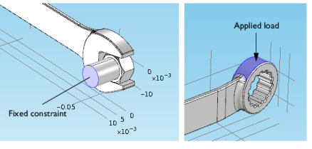
In the Model Builder window, under Component 1 (comp1) right-click Solid Mechanics (solid) and choose Fixed Constraint.
2
Click the  Wireframe Rendering button in the Graphics toolbar.
3
Boundary Load 1
1
In the Physics toolbar, click  Boundaries and choose Boundary Load.
2
3
In the Settings window for Boundary Load, locate the Force section.
4
From the Load type list, choose Total force.
5
Specify the Ftot vector as
The minus sign means that the force is applied downward.
Mesh 1
Use finer mesh because the geometry contains small edges and faces.
1
In the Model Builder window, under Component 1 (comp1) click Mesh 1.
2
In the Settings window for Mesh, locate the Physics-Controlled Mesh section.
3
From the Element size list, choose Finer.
4
Click  Build All.
Study 1
If your computer has more than 4 GB of RAM, you can skip the following four instructions and continue directly to compute the solution. Otherwise, follow these steps to use an iterative solver:
Solution 1 (sol1)
1
In the Study toolbar, click  Show Default Solver.
2
In the Model Builder window, expand the Solution 1 (sol1) node.
3
In the Model Builder window, expand the Study 1>Solver Configurations>Solution 1 (sol1)>Stationary Solver 1 node.
4
Right-click Study 1>Solver Configurations>Solution 1 (sol1)>Stationary Solver 1>Suggested Iterative Solver (solid) and choose Enable.
Iterative solvers require less memory but can be less robust than direct solvers.
Compute the solution
In the Study toolbar, click  Compute.
Results
Stress (solid)
The default plot group shows the von Mises stress in a Surface plot with the displacement visualized using a Deformation subnode. Change to a more suitable unit as follows.
Surface 1
1
In the Model Builder window, expand the Results>Stress (solid) node, then click Surface 1.
2
In the Settings window for Surface, locate the Expression section.
3
From the Unit list, choose MPa.
4
In the Stress (solid) toolbar, click  Plot.
5
Click the  Zoom Extents button in the Graphics toolbar.
First Principal Strain
1
In the Model Builder window, right-click Stress (solid) and choose Duplicate.
2
In the Settings window for 3D Plot Group, type First Principal Strain in the Label text field.
Surface 1
1
In the Model Builder window, expand the First Principal Strain node, then click Surface 1.
2
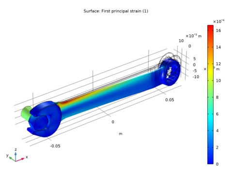
In the Settings window for Surface, click Replace Expression in the upper-right corner of the Expression section. From the menu, choose Component 1 (comp1)>Solid Mechanics>Strain>Principal strains>solid.ep1 - First principal strain.
3
In the First Principal Strain toolbar, click  Plot.
Notice that the maximum principal strain is lower than 2%, a result that satisfies the small strain assumption.