PDF

2D Lithium-Ion Battery
Introduction
This tutorial is a two-dimensional model of a lithium-ion battery. The cell geometry could be a small part of an experimental cell, but here it is only meant to demonstrate a 2D model setup. The battery contains a positive porous electrode, electrolyte, a negative lithium metal electrode, and a current collector. This cell configuration is sometimes called a “half-cell”, since the lithium metal electrode has negligible impact on cell voltage and polarization. A more realistic 2D geometry is exemplified in the model Edge Effects in a Spirally Wound Lithium-Ion Battery available in the Battery Design Module Application Library.
For a detailed description of this model, in particular step-by-step instructions with several screen shots showing how to build it, see the book Introduction to the Battery Design Module.
Model Definition
The 3D cell geometry is shown in Figure 1. Due to symmetry along the height of the battery, the 3D geometry can be modeled using a 2D cross section. Figure 1 shows the positioning of the positive and negative electrodes, and the current collector attached to the positive electrode. The positive electrode is porous and the negative electrode consists of lithium metal. The modeled 2D cross section is highlighted in the light blue section in the rightmost figure of Figure 1.
Since the electrochemical reaction only takes place at the surface of the lithium metal, and the electronic conductivity is very high, the thickness of the metal is neglected in the model geometry. The modeled 2D cell geometry is shown in Figure 2. During discharge, the positive electrode acts as the cathode and the contact of the metallic tab acts as a current collector. The negative lithium metal electrode acts as the anode and current feeder.
The model defines and solves the current and material balances in the lithium-ion battery. The intercalation of lithium inside the particles in the positive electrode is solved using a fourth independent variable for the particle radius (x, y, and t are the other three). The reaction kinetics and the intercalation are coupled to the material and current balances at the surface of the particles. The model equations are found in the Battery Design Module User’s Guide. The model equations were originally formulated for 1D simulations by John Newman and his coworkers at the University of California at Berkeley.
Figure 1: 3D model geometry of Lithium-ion model.
Figure 2: A 2D cross-sectional model geometry with the thickness of the negative lithium metal electrode neglected.
The purpose of the 2D simulation is to reveal the distribution of the depth of discharge in the positive electrode, as a function of discharge time. This distribution depends on the positioning of the current collector and the thickness of the positive electrode and electrolyte, in combination with the electrode kinetics and transport properties.
Results and Discussion
Figure 3 shows the lithium concentration distribution at the surface of the positive electrode particles at time equal to 2700 s during the simulation. The initial concentration of lithium in the positive electrode is 10,000 mol/m3. During the discharge, as lithium is dissolved on the negative lithium metal electrode, the concentration in the positive electrode increases.
Figure 3: Lithium concentration at the surface of the electrode particles at 2700 s.
The concentration in the positive electrode particles at two selected locations within the positive porous electrode is displayed in Figure 4. Both selections are positioned at the same distance from the electrolyte domain but at different distances from the current collector. The blue line displays the concentration at the location furthest away from the current collector and shows that less discharge has taken place there (concentration lower). This is consistent with Figure 3.The difference in concentration between the particle center and surface indicate limitations in the lithium transport within the particles.
Figure 4: Lithium concentration in the positive electrode particles at two selected positions, (x=0.5 mm, y=0.1 mm) and (x=0.5 mm, y=0.55 mm), within the model geometry.
The time-dependent cell voltage predicted by the model during the discharge simulation is shown in Figure 5.
Figure 5: Cell voltage variation during discharge.
Application Library path: Battery_Design_Module/Batteries,_Lithium-Ion/li_battery_tutorial_2d
Modeling Instructions
From the File menu, choose New.
New
In the New window, click  Model Wizard.
Model Wizard
1
In the Model Wizard window, click  2D.
2
In the Select Physics tree, select Electrochemistry>Batteries>Lithium-Ion Battery (liion).
3
Click Add.
4
Click  Study.
5
In the Select Study tree, select Preset Studies for Selected Physics Interfaces>Time Dependent with Initialization.
(The Time Dependent with Initialization study will perform a time-dependent simulation, using a initialization study step to calculate the initial potentials in the cell.)
6
Geometry 1
Insert a prepared geometry sequence from a file. After insertion you can study each geometry step in the sequence Appendix — Geometry Modeling Instructions.
1
In the Geometry toolbar, click  Insert Sequence.
2
3
In the Geometry toolbar, click  Build All.
4
Click the  Zoom Extents button in the Graphics toolbar.
Materials
Use the Battery Material Library to set up the material properties for the electrolyte and electrode materials. By adding the electrolyte material to the model first, this material becomes the default material for all domains. (In the Materials node, cEeqref denotes the maximum lithium concentration in the active material.)
Add Material
1
In the Home toolbar, click  Add Material to open the Add Material window.
2
Go to the Add Material window.
3
In the tree, select Battery>Electrolytes>LiPF6 in 1:2 EC:DMC and p(VdF-HFP) (Polymer electrolyte, Li-ion Battery).
4
Click Add to Component in the window toolbar.
5
In the tree, select Battery>Electrodes>LMO Electrode, LiMn2O4 Spinel (Positive, Li-ion Battery).
6
Click Add to Component in the window toolbar.
7
In the Home toolbar, click  Add Material to close the Add Material window.
Materials
LMO Electrode, LiMn2O4 Spinel (Positive, Li-ion Battery) (mat2)
The first material you added was assigned by default to all domains. Override this default selection by assigning the electrode material to domain 1.
1
The LMO material node will now be marked with a small red cross in the model tree, indicating missing material properties. This is expected at this point and will be resolved when setting up the physics for the porous electrode node.
Lithium-Ion Battery (liion)
An Electrolyte node has already been added to the model by default. Now set up the physics in the positive porous electrode.
Porous Electrode 1
1
In the Model Builder window, under Component 1 (comp1) right-click Lithium-Ion Battery (liion) and choose Porous Electrode.
2
The porous electrode contains both an electrode and an electrolyte phase. You therefore need to assign different materials to the different phases. By default, the material properties for each phase will be taken from the material assigned to the domain under Materials, which in this case is LMO electrode material. You hence need to set the electrolyte phase material selection manually.
3
In the Settings window for Porous Electrode, locate the Electrolyte Properties section.
4
From the Electrolyte material list, choose LiPF6 in 1:2 EC:DMC and p(VdF-HFP) (Polymer electrolyte, Li-ion Battery) (mat1).
In this model we will assume that the porous electrode consists of a mix of 40% electrode and 15% inert binder material. The remaining volume is filled up with electrolyte.
5
Locate the Porous Matrix Properties section. In the εl text field, type 1-0.4-0.15.
Materials
LMO Electrode, LiMn2O4 Spinel (Positive, Li-ion Battery) (mat2)
The small red cross on the LMO material node should now have disappeared in the model tree.
Lithium-Ion Battery (liion)
Particle Intercalation 1
The Porous Electrode has two child nodes added by default. The Particle Intercalation node adds an extra dimension to the selected domain, and solves for the diffusion of solid lithium in this extra dimension, assuming spherical particles. Keep the default settings for this node.
Porous Electrode Reaction 1
The Porous Electrode Reaction node sets up the equilibrium potential, kinetics and stoichiometry of the lithium insertion reaction occurring at the interface between the electrolyte and electrode phases within the porous matrix. Keep the default settings also for this node.
Electrode Current 1
Finish the model by setting up the boundary conditions. At the positive electrode, set an average current density.
1
In the Model Builder window, expand the Porous Electrode 1 node.
2
Right-click Lithium-Ion Battery (liion) and choose Electrode>Electrode Current.
3
4
In the Settings window for Electrode Current, locate the Electrode Current section.
5
From the list, choose Average current density.
6
In the is,average text field, type -50[A/m^2].
Electrode Surface 1
The negative electrode is a lithium metal foil. This is modeled as a planar electrode using the Electrode Surface node.
1
In the Physics toolbar, click  Boundaries and choose Electrode Surface.
2
Electrode Reaction 1
For this reaction, set the equilibrium potential to 0[V].
1
In the Model Builder window, expand the Electrode Surface 1 node, then click Electrode Reaction 1.
2
In the Settings window for Electrode Reaction, locate the Equilibrium Potential section.
3
From the Eeq list, choose User defined. Click to expand the Heat of Reaction section. From the dEeq/dT list, choose User defined.
Mesh 1
Use the default physics-controlled mesh for this model.
1
In the Model Builder window, under Component 1 (comp1) right-click Mesh 1 and choose Build All.
The generated mesh should look as follows:
Study 1
Step 2: Time Dependent
Set up a 2700 s time-dependent solver to store the solution at 10 s intervals during the first 100 s, and 100 s intervals during the last 2600 s.
1
In the Model Builder window, under Study 1 click Step 2: Time Dependent.
2
In the Settings window for Time Dependent, locate the Study Settings section.
3
Click  Range (the small icon to the right of the Times text field).
4
In the Range dialog box, type 10 in the Step text field.
5
In the Stop text field, type 100.
6
Click Replace.
7
In the Settings window for Time Dependent, locate the Study Settings section.
8
Click  Range again.
9
In the Range dialog box, type 200 in the Start text field.
10
In the Step text field, type 100.
11
In the Stop text field, type 2700.
12
Click Add.
(Alternatively, you may also type in the expression range(0,10,100) range(200,100,2700) directly in the Times text field.)
13
In the Home toolbar, click  Compute.
Results
Battery Voltage
A plot of the electrode voltage where you set the electrode current condition is created by default. Since you grounded the other electrode this equals the battery voltage during the simulation(Figure 5):
1
In the Settings window for 1D Plot Group, type Battery Voltage in the Label text field.
2
In the Battery Voltage toolbar, click  Plot.
Lithium Concentration on Particle Surface
The following steps create a plot of the lithium concentration at the surface of the electrode particles at 2700 s (Figure 3):
1
In the Home toolbar, click  Add Plot Group and choose 2D Plot Group.
2
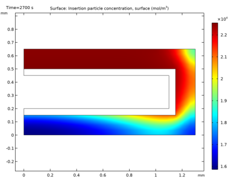
In the Settings window for 2D Plot Group, type Lithium Concentration on Particle Surface in the Label text field.
Surface 1
1
Right-click Lithium Concentration on Particle Surface and choose Surface.
2
In the Settings window for Surface, click Replace Expression in the upper-right corner of the Expression section. From the menu, choose Component 1 (comp1)>Lithium-Ion Battery>Particle intercalation>liion.cs_surface - Insertion particle concentration, surface - mol/m³.
3
In the Lithium Concentration on Particle Surface toolbar, click  Plot.
Study 1/Solution 1 (3) (sol1)
As mentioned before, the Particle Intercalation node adds an extra dimension to the porous electrode domain, and solves for the concentration of solid lithium in this extra dimension. Proceed as follows to create a plot of the lithium concentration in the particles in the positive electrode (Figure 4). In order to do this you need to first create a Solution dataset that refers to the extra dimension.
1
In the Results toolbar, click  More Datasets and choose Solution.
2
In the Settings window for Solution, locate the Solution section.
3
From the Component list, choose Extra Dimension from Particle Intercalation 1 (liion_pce1_pin1_xdim).
Lithium Concentration in Positive Electrode Particles
1
In the Results toolbar, click  1D Plot Group.
2
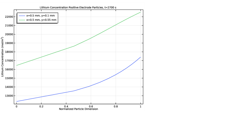
In the Settings window for 1D Plot Group, type Lithium Concentration in Positive Electrode Particles in the Label text field.
3
Locate the Data section. From the Dataset list, choose None.
Line Graph 1
1
Right-click Lithium Concentration in Positive Electrode Particles and choose Line Graph.
2
In the Settings window for Line Graph, locate the Data section.
3
From the Dataset list, choose Study 1/Solution 1 (3) (sol1).
4
From the Time selection list, choose Last.
5
Locate the Selection section. From the Selection list, choose All domains.
The atxd2() operator is used to specify the x and y coordinate in the battery geometry.
6
Locate the y-Axis Data section. In the Expression text field, type comp1.atxd2(5e-4,1e-4,liion.cs_pce1).
7
Click to expand the Legends section. Select the Show legends check box.
8
From the Legends list, choose Manual.
9
Line Graph 2
1
Right-click Line Graph 1 and choose Duplicate.
2
In the Settings window for Line Graph, locate the y-Axis Data section.
3
In the Expression text field, type comp1.atxd2(5e-4,5.5e-4,liion.cs_pce1).
4
Locate the Legends section. In the table, enter the following settings:
Lithium Concentration in Positive Electrode Particles
1
In the Model Builder window, click Lithium Concentration in Positive Electrode Particles.
2
In the Settings window for 1D Plot Group, click to expand the Title section.
3
From the Title type list, choose Manual.
4
In the Title text area, type Lithium Concentration Positive Electrode Particles, t=2700 s.
5
Locate the Plot Settings section. Select the x-axis label check box.
6
In the associated text field, type Normalized Particle Dimension.
7
Select the y-axis label check box.
8
In the associated text field, type Lithium Concentration (mol/m<sup>3</sup>).
9
Locate the Legend section. From the Position list, choose Upper left.
10
In the Lithium Concentration in Positive Electrode Particles toolbar, click  Plot.
 
Appendix — Geometry Modeling Instructions
From the File menu, choose New.
New
In the New window, click  Blank Model.
Add Component
In the Home toolbar, click  Add Component and choose 2D.
Geometry 1
1
In the Settings window for Geometry, locate the Units section.
2
From the Length unit list, choose mm.
Rectangle 1 (r1)
1
In the Geometry toolbar, click  Rectangle.
2
In the Settings window for Rectangle, locate the Size and Shape section.
3
In the Width text field, type 1.3.
4
In the Height text field, type 0.65.
Rectangle 2 (r2)
1
In the Geometry toolbar, click  Rectangle.
2
In the Settings window for Rectangle, locate the Size and Shape section.
3
In the Width text field, type 1.15.
4
In the Height text field, type 0.35.
5
Locate the Position section. In the y text field, type 0.15.
Rectangle 3 (r3)
1
In the Geometry toolbar, click  Rectangle.
2
In the Settings window for Rectangle, locate the Size and Shape section.
3
In the Width text field, type 1.1.
4
In the Height text field, type 0.25.
5
Locate the Position section. In the y text field, type 0.2.
Difference 1 (dif1)
1
In the Geometry toolbar, click  Booleans and Partitions and choose Difference.
2
Select the objects r1 and r2 only.
3
In the Settings window for Difference, locate the Difference section.
4
Find the Objects to subtract subsection. Select the  Activate Selection toggle button.
5
Point 1 (pt1)
1
In the Geometry toolbar, click  Point.
2
In the Settings window for Point, locate the Point section.
3
In the x text field, type 1.
4
In the y text field, type 0.65.
Form Union (fin)
1
In the Model Builder window, click Form Union (fin).
2
In the Settings window for Form Union/Assembly, click  Build Selected.