|
|
|
|
1
|
|
2
|
|
3
|
Click Add.
|
|
4
|
Click
|
|
5
|
|
6
|
Click
|
|
1
|
|
2
|
Browse to the model’s Application Libraries folder and double-click the file multiturn_coil_asymmetric_conductor_geom_sequence.mph.
|
|
3
|
|
4
|
|
1
|
|
2
|
|
3
|
Locate the Selections of Resulting Entities section. Select the Resulting objects selection check box.
|
|
1
|
|
2
|
|
3
|
Locate the Selections of Resulting Entities section. Select the Resulting objects selection check box.
|
|
4
|
|
5
|
|
7
|
|
1
|
In the Model Builder window, under Component 1 (comp1) right-click Magnetic Fields (mf) and choose Group by Space Dimension.
|
|
2
|
|
1
|
In the Model Builder window, under Component 1 (comp1)>Magnetic Fields (mf) right-click Domains and choose Coil.
|
|
2
|
|
3
|
|
4
|
|
5
|
|
6
|
|
1
|
In the Model Builder window, expand the Component 1 (comp1)>Magnetic Fields (mf)>Domains>Coil 1>Geometry Analysis 1 node, then click Input 1.
|
|
1
|
|
2
|
|
3
|
In the tree, select Built-in>Air.
|
|
4
|
|
5
|
|
1
|
|
1
|
|
2
|
|
3
|
|
4
|
|
5
|
|
6
|
|
7
|
Click OK.
|
|
1
|
|
2
|
|
3
|
|
4
|
|
5
|
|
6
|
|
1
|
|
2
|
|
3
|
|
4
|
|
5
|
|
6
|
|
1
|
|
2
|
|
1
|
|
1
|
|
2
|
|
3
|
|
4
|
|
5
|
|
6
|
|
7
|
|
1
|
|
2
|
|
3
|
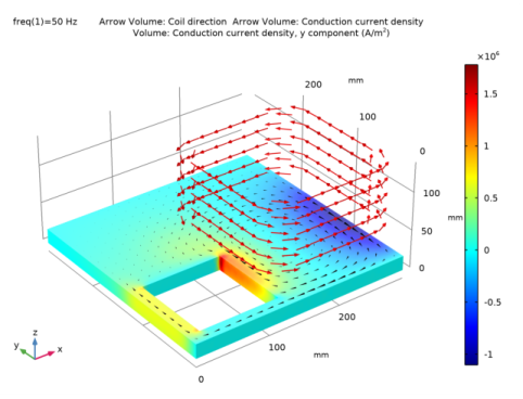
In the Settings window for 3D Plot Group, type Coil Direction and Induced Current Density, 50 Hz in the Label text field.
|
|
4
|
|
1
|
|
2
|
|
3
|
|
1
|
|
2
|
In the Settings window for Arrow Volume, click Replace Expression in the upper-right corner of the Expression section. From the menu, choose Component 1 (comp1)>Magnetic Fields>Coil parameters>mf.coil1.eCoilx,...,mf.coil1.eCoilz - Coil direction.
|
|
3
|
Locate the Arrow Positioning section. Find the x grid points subsection. In the Points text field, type 10.
|
|
4
|
|
5
|
|
6
|
|
1
|
|
2
|
|
3
|
|
1
|
|
2
|
In the Settings window for Arrow Volume, click Replace Expression in the upper-right corner of the Expression section. From the menu, choose Component 1 (comp1)>Magnetic Fields>Currents and charge>mf.Jix,...,mf.Jiz - Conduction current density.
|
|
3
|
Locate the Arrow Positioning section. Find the x grid points subsection. In the Points text field, type 20.
|
|
4
|
|
5
|
|
6
|
|
7
|
|
8
|
|
1
|
|
2
|
|
3
|
|
1
|
|
2
|
In the Settings window for Volume, click Replace Expression in the upper-right corner of the Expression section. From the menu, choose Component 1 (comp1)>Magnetic Fields>Currents and charge>Conduction current density - A/m²>mf.Jiy - Conduction current density, y component.
|
|
1
|
|
2
|
|
3
|
|
4
|
|
1
|
|
2
|
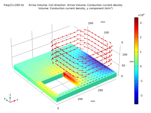
In the Settings window for 3D Plot Group, type Coil Direction and Induced Current Density, 200 Hz in the Label text field.
|
|
3
|
|
4
|
|
1
|
|
2
|
|
3
|
|
4
|
|
1
|
|
2
|
|
3
|
|
4
|
|
1
|
|
2
|
|
3
|
Click Import.
|
|
4
|
Browse to the model’s Application Libraries folder and double-click the file multiturn_coil_asymmetric_conductor_table1.txt.
|
|
5
|
|
1
|
|
2
|
|
3
|
Click Import.
|
|
4
|
Browse to the model’s Application Libraries folder and double-click the file multiturn_coil_asymmetric_conductor_table2.txt.
|
|
5
|
|
1
|
|
2
|
|
3
|
|
4
|
|
5
|
|
6
|
|
7
|
|
1
|
|
2
|
|
1
|
|
2
|
|
3
|
|
4
|
|
5
|
|
6
|
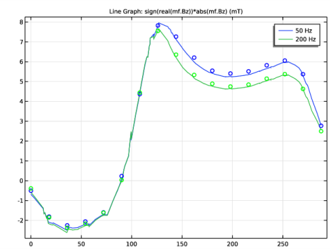
Locate the Coloring and Style section. Find the Line style subsection. From the Line list, choose None.
|
|
7
|
|
8
|
|
9
|
|
1
|
|
2
|
|
3
|
|
4
|
|
5
|
|
1
|
|
2
|
|
3
|
|
4
|
|
5
|
|
6
|
|
1
|
|
2
|
|
1
|
|
2
|
|
3
|
|
4
|
|
5
|
|
6
|
|
7
|
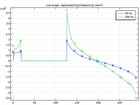
Locate the Coloring and Style section. Find the Line style subsection. From the Line list, choose None.
|
|
8
|
|
9
|
|
10
|
|
1
|
|
2
|
|
3
|
|
4
|