where k and
f are material parameters,
Δτ is the maximum shear stress range on a plane, and
σn is the largest normal stress on the same plane. The plane that maximizes the left-hand side of the equation is considered to be critical.
The fatigue usage factor, fus, is the ratio between the left-hand side of the Findley criterion and the material parameter
f. A value below
1 means that the component is loaded below the fatigue limit. For high compressive stress states the contribution from the normal stress can dominate the criteria predicting a negative
fus. In those cases, the fatigue usage factor is set to zero.
To find the two material parameters k and
f, two fatigue tests with different loading conditions are needed. This can, for example, be pure tension and pure torsion, but there are also other possibilities. For axial loading, the following relation is valid:
Here, σmax and
σmin are the maximum and minimum stresses at the fatigue limit, respectively (that is, infinite life). Tests with two different R values can thus be used to determine
k and
f. In a pure (fully reversed) torsion test with an amplitude
τa of the torsional shear stress, the corresponding relation is
If only uniaxial test data with a single R value is available, it is possible to estimate
k from the ratio between the fatigue limits under different conditions for a similar material.
where τmax is the maximum shear stress,
σH is the hydrostatic stress, while
aDV and
bDV are material constants.
The stress state at the macroscopic level, Σij, differs from the stress state at the microscopic level,
σij. At the macroscopic level the material is homogeneous, while at the microscopic level it is inhomogeneous. According to the Dang Van theory, the two stress tensors are related to each other via a plastic shakedown that prevents crack growth from a critical grain to the neighboring one. Affected by the multiaxial loading, the material undergoes combined kinematic and isotropic hardening and as a result the center and the radius of the yield surface changes. The center of the smallest hypersphere in stress space which encloses the entire load history determines the residual stress tensor of the shakedown. It is a 6 dimensional hypersphere with the axes

,

,

,
sxy,
syz, and
sxz, where
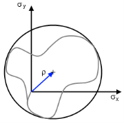
sij is the deviatoric stress tensor. The resulting microscopic stress is given by
where ρ is the residual stress tensor of the shakedown. A schematic description of the residual stress tensor for a biaxial case is shown in
Figure 3-13.
where σ1,
σ2, and
σ3 are the principal stresses. The function argument
t denotes the time dependence of the stress variables. The fatigue usage factor is finally computed as