For multiaxial cases many of the most popular fatigue criteria are based on the concept of a critical plane. A critical plane is a plane with a certain orientation in a point in the loaded structure that maximizes some stress or strain expression. Different models use different criteria to determine the critical plane. A successful model must be able to predict both the fatigue life and the dominant failure plane. For nonproportional loading the orientation of the critical planes is nontrivial and the loading history needs to be examined for all possible directions in order to find the critical plane.
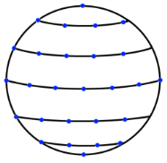
Consider the upper half of the unit sphere. The meridian from the north pole to the equator is subdivided into N equally spaced segments, giving
N + 1 points. The length of such a segment is
π/2N. From each point a circle of latitude is constructed. This circle is subdivided into M equally sized segments, having approximately the length
π/2N. Thus, the number of direction points on each circle of latitude will differ, see
Figure 3-6. The total number of normals generated in this manner is approximately 3
N2.
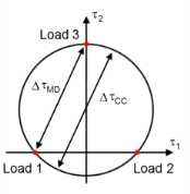
On a given plane the normal stress is a scalar, but the shear stress is a two-dimensional vector. This requires an interpretation of shear stress range, Δτ. For a multiaxial case there is no unique definition of what the maximum shear stress range is. The most strict interpretation is that
Δτ is the diameter of the smallest circle that circumscribing the path that the
τ vector creates during a load cycle,
ΔτCC. This calculation is nontrivial, however, and takes significant computer resources. An alternative is to use the maximum distance between any two points on the path instead,
ΔτMD. This simplified procedure could, in extreme cases, underestimate
Δτ by 13%. Evaluation of shear range according to both methods is shown in
Figure 3-7.