where Δε is the strain range evaluated as the difference between the largest and the smallest strain experienced during a fatigue cycle.
where ε1 is the largest principal strain,
ε3 is the smallest principal strain.
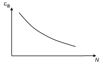
The E-N curve is a relation between strain amplitude, εa, and fatigue life,
N, that can be summarized on the form
where fEN is the function. At low strain the fatigue life is limited by a
Cycle Cutoff. At high strain when the strain amplitude exceeds the highest strain as defined by the E-N curve the fatigue life cannot be determined. No results are computed in such regions. This is demonstrated in
Figure 3-12.
where  is the accumulated inelastic strain in a load cycle,
  and c
and c are material constants, and 2
Nf is the number of load reversals to failure. Two reversals are equal to one cycle, so
Nf is the number of cycles to failure. The fatigue relation in the original work (
Ref. 5) was used for low-cycle fatigue prediction in metals and, therefore,

was taken as the plastic strain range.
Many other fatigue models are based on the work by Coffin-Manson. These, however, express the damaging inelastic strain in various ways such as equivalent creep strain range, plastic shear strain, equivalent secondary creep, and others (Ref. 4). The original relation has been generalized in the Fatigue Module so that the accumulated inelastic strain can be evaluated in several ways depending on the selected
Strain type in the
Fatigue Model Selection section. The different options are shown in
Table 3-4 where

is the equivalent creep strain range and

is the equivalent plastic strain range. When
User defined is used as
Strain type, the strain variable must be specified.
where σ'
f is the fatigue strength coefficient,
b is the fatigue strength exponent,
ε'
f is the fatigue ductility coefficient,
c is the fatigue ductility exponent, and
E is Young’s modulus. 2
Nf is the number of load reversals, and thus
Nf is the number of full cycles to failure at a strain amplitude of
εa. At low strains the fatigue life is limited by a
Cycle Cutoff.
where σm is the mean stress of the load cycle. Since stress is a second order tensor and the mean stress is a scalar, the evaluation of the mean stress is based on the principal stress according to