Local Orientations
Many stress and strain tensor components are available both in local and global directions. Some examples are:
solid.sxy — Cauchy stress with respect to the global spatial coordinate system
solid.sl12 — Cauchy stress with respect to the local coordinate system of the material.
solid.SXY — Second Piola-Kirchhoff stress with respect to the global material coordinate system
solid.Sl12 — Second Piola-Kirchhoff stress with respect to the local coordinate system of the material
solid.eXY — Strain with respect to the global material coordinate system
solid.el12 — the local coordinate system of the material
As can be seen, tensor component indices containing the names of a coordinate directions has orientations along those axes. Components in local directions contain the letter ‘l’ and numerical indices.
The local directions are defined by the coordinate system attached to a material model. For most material models, you can select a local coordinate system in the Coordinate System Selection section of its settings. The purpose of this selection is twofold:
When the material is isotropic, you can utilize the local coordinate system just for the second purpose. In this case, the results of the analysis itself are independent of the selected coordinate system. It just provides a transformation to be utilized during result evaluation. If you want to change the orientations for the local components of the tensors, you do not have to solve the study again. Instead, you select the new coordinate system in the material model node, and then run Update Solution () for the study or studies where you want the new definition to be applied.
Updating a Solution in the COMSOL Multiphysics Reference Manual.
Adding Your Own Transformations
If there are no suitable local coordinate system variables defined from the physics interface itself, you can create your own transformations. Under Definitions>Variable Utilities, add a Vector Transform or Matrix Transform depending on the type of object you are going to transform.
These nodes provide a large degree of flexibility in defining various types of transforms, but for a pure rotation into a new coordinate system, the settings are straightforward. Do the following:
1
2
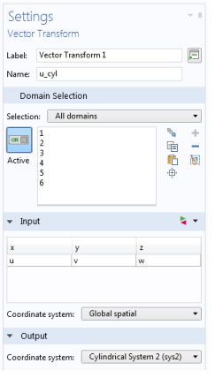
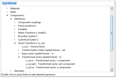
In the Input section, enter the components of the vector or tensor to be transformed. In most cases, you can pick it using Replace Expression ().
3
In the Vector Transform or Matrix Transform node, select the local coordinate system in the Output section. In the latter node, select it twice.
4
5
Figure 2-25: Example of settings for transforming the displacement vector to a cylindrical coordinate system.
If you define the transformation after the study was solved, you will need to run Update Solution () for the study or studies where you want to access the transformed variables.
You can now access the new transformed quantities for various type of result presentation. They are accessible under Definitions in the Replace Expression dialog.
Figure 2-26: Picking a transformed result in the Replace Expression dialog.
Vector Transform and Matrix Transform in the COMSOL Multiphysics Reference Manual.