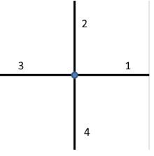
To model such joints, you use the Beam End Release node. In that node, you can specify that some degrees of freedom are decoupled at a certain point.
If you want to describe non-default types of connections, you need to add one or more Edge Group subnodes to the
Beam End Release node. If just a single beam is disconnected, as in
Figure 8-4, then you need a single edge group in which you select the other three beams (2, 3, and 4).
To describe the case in Figure 8-5, you add two edge groups. You then select beams 1 and 3 in the first one, and beams 2 and 4 in the second one.
There are, however, some cases when the orientations can become ambiguous. Consider, for example, a 2D case where both the X-translation and the out-of-plane rotation are decoupled where two beams meet. This situation is shown in
Figure 8-6. Since the rotation is now different in the two beams, so is the definition of a rotated
X direction. Depending on the physical arrangement, the translational sliding motion can follow either of the two connected beams. In the section
Edge Defining the Local Direction in the settings for
Beam End Release, you can select the edge that controls the rotation of the coordinate system under finite rotations.
