Theory for the Heat Pipe Component
Heat pipes are devices which use the latent heat of evaporation and condensation of a fluid to transfer heat from a source to a sink with high efficiency.
Device Description
Although various geometric configurations are available, a heat pipe includes a vapor channel delimited by a solid wall, with a porous wick in between, see Figure 4-8 below.
Figure 4-8: Heat pipe components.
The working fluid flows from the hot side to the cold side of the heat pipe under vapor state in the core channel, and under liquid state on the way back through the porous wick by capillary action. It evaporates when leaving the wick to the core channel on the hot side, named evaporator side, and condensates when entering the wick on the cold side, named condenser side.
The heat is transferred by conduction through the wall, and by conduction and convection in the wick and in the vapor channel. The latent heat absorbed and released by the evaporation and condensation of the working fluid makes heat pipes very effective heat transfer devices, with large effective thermal conductivities.
Network Representation
Whereas the full modeling of heat transfer in a heat pipe necessitates the modeling of several processes (vapor transport in the channel, liquid transport in the porous wick, and phase change at the interface between the wick and the vapor channel), a network representation allows to estimate the temperature drop between the evaporator and the condenser sides by considering a set of relevant thermal resistances.
By making the analogy with electrical circuits, the total thermal resistance R (SI unit: W/K) is expressed as:
where
with
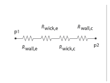
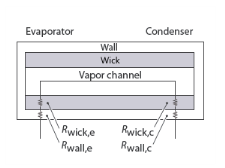
Rwall,e the thermal resistance of the wall on evaporator side
Rwick,e the thermal resistance of the wick on evaporator side
Rlv,e the thermal resistance of the liquid-vapor interface on evaporator side
Rlv,c the thermal resistance of the liquid-vapor interface on condenser side
Rwick,c the thermal resistance of the wick on condenser side
Rwall,c the thermal resistance of the wall on condenser side
Rv,a the thermal resistance of the vapor channel in adiabatic section
Rwick,a the thermal resistance of the wick in adiabatic section
Rwall,a the thermal resistance of the wall in adiabatic section
By making assumptions on the relative magnitude of the thermal resistances, the expression of R reduces to:
And the temperature drop ΔTcondenser − Tevaporator is then expressed as
where P (SI unit: W) is the operating power of the heat pipe.
This corresponds to the following network representation:
Figure 4-9: Thermal network representation of a heat pipe.
See Ref. 17 for details about the network representation of heat pipes and the expressions of effective thermal conductivity of the wick used to express its thermal resistance.