Settings and Properties Windows for Feature Nodes
Settings Window
For all operating systems, and when any node is clicked in the Model Builder (except a few container nodes such as Definitions and Datasets), a corresponding Settings window opens with the same name as the node. The Settings window contains settings for defining operations and properties specific to a node, as shown in Figure 3-3.
Figure 3-3: An example of a node Settings window. In this example, the Settings window for the Component node opens when the node of the same name is clicked. You can also toggle between the Settings and Properties window from the context menu.
Settings Window Functionality
When an operation or property is updated in the Settings window, its effect on the model is displayed in the Graphics window either instantaneously or by clicking the applicable button, which are available in some of the Settings window toolbars. If you update settings for the physics interfaces and features, you must recompute the solution to reflect the changes in the physics interface and features.
For most sequences, you can run the sequence by right-clicking the top node of the branch and selecting Build All
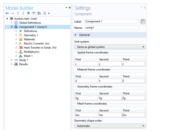
 (geometry) and Build (mesh), Compute  (studies), or Plot (plot groups), or by pressing F8. These buttons are also on the Settings window and in the respective toolbars.
To select the parts of the model to define in a specific Settings window, select the relevant geometric entities directly in the displayed model in the Graphics window, from the Selection List window, or as, for example, All domains in the Settings window.
Labels and Names in the Settings Window
Every Settings window has the option to change the node Label. The Label is the default node description (it defaults to the node Type followed by an index suffix). For example, it might be the Electric Currents interface, or in Figure 3-3 it is Component. You can also right-click and choose Rename or press F2.
Some Settings windows have the option to change the Name. These include physics interfaces, components (as in Figure 3-3), multiphysics couplings, and some Definitions features. The Name is used primarily as a scope prefix for variables defined by the physics interface. Refer to such physics interface variables in expressions using the pattern <name>.<variable_name>. In order to distinguish between variables belonging to different physics interfaces, the name string must be unique. Only letters, numbers, and underscores (_) are permitted in the Name field. The first character must begin with a lowercase or uppercase letter (a–z or A–Z). All other characters in the Name must be a lowercase or uppercase letter, a number between 0 and 9, or an underscore (_). See Variable Naming Convention and Namespace for more information.
In most Settings windows, there is also a Create Shortcut button () next to the Label field. Click it (or press Ctrl+K) to create a shortcut to that node for use in the Application Builder (see the Application Builder documentation for more information). If a shortcut already exists, you can click the Rename Shortcut button () (or press Ctrl+K) to rename the shortcut.
Properties Window
Figure 3-4: An example of a node Properties window. In this example, the Properties window for the Component node opens when you right-click the node and select Properties from the context menu. You can also toggle between the Settings and Properties window from this context menu.
The Properties window () in Figure 3-4 is accessed by right-clicking the node and choosing Properties from the context menu. The information listed includes the Label, Name, Tag, and the Node Properties.
The Label can be edited on the Settings window. The default or edited name is displayed here but cannot be changed in this window.
The Name is available for Component, functions and other nodes under Definitions, Material, and physics interface and multiphysics coupling nodes. You can edit the name on the Settings window for Component nodes, the main physics interface nodes, and for some functions and other nodes under Definitions, where the names servers as an identifier in the namespace for variables or as the function name, for example.
The Tag is unique for each node and is assigned automatically. Tags are primarily used when running COMSOL models in Java or MATLAB. To display the Tag in the Model Builder, click Model Builder Node Text  on the toolbar and choose Tag. See Displaying Node Names, Tags, and Types in the Model Builder for more information.
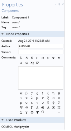
The Node Properties section includes the following information: Created, Author, Version, and Comments (the root node is a special case; see The Root Settings and Properties Windows). The Created field is automatically assigned by the software. You can edit the Author, Version, and Comments fields in this window. For the Comments field, you can add formatting and special characters that will appear in reports. This information can also be included when creating Reports.