|
•
|
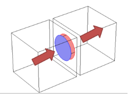
The inlet of the device is an outlet boundary condition for the modeled domain. For this outlet side, on dev_in, a pressure condition is set. The value of the pressure is set to the sum of the mean value of the pressure on dev_out and the pressure drop across the device. The pressure drop is calculated from a lumped curve using the flow rate evaluated on dev_in.
|
|
•
|
For the inlet side, on dev_out, a pressure boundary condition is defined. The pressure value is set so that the flow rate is equal on dev_in and dev_out. An ODE is added to compute the pressure value.
|
|
•
|
When a turbulence model with transport equations for the turbulence quantities is applied, the turbulent kinetic energy, k, and dissipation rate, ε, specific dissipation rate, ω, or turbulent relative fluctuations, ζ, must be specified on the downstream side of the fan. The turbulence conditions are specific to the design and operating conditions of the fan. A reference velocity scale Uref is available in order to set default values.
|
|
|
In both cases, the boundary condition implementation follows the Pressure Boundary Condition for outlet or inlet with the Suppress backflow option.
|
|
|
See Interior Fan for node settings.
|