You are viewing the documentation for an older COMSOL version. The latest version is
available here.
Use the Release from Grid node to release rays from a user-defined grid of points.
See Release for information on the following sections:
Release Times, Ray Direction Vector,
Initial Ray Frequency,
Initial Phase,
Initial Intensity,
Initial Radii of Curvature,
Total Source Power, and
Initial Value of Auxiliary Dependent Variables.
Select an option from the Grid type list:
All combinations (the default),
Specified combinations,
Cylindrical (3D only), or
Hexapolar (3D only).
For All combinations and
Specified combinations enter
Initial coordinates based on space dimension (
qx,0,
qy,0, and
qz,0 for 3D components) for the ray positions or click the
Range button (

) to select and define a range of specific coordinates.
If Specified combinations is selected, the number of initial coordinates entered for each space dimension must be equal, and the total number of rays released is equal to the length of one of the lists of initial coordinates. If
All combinations is selected, the total number of rays released is equal to the product of the lengths of each list of initial coordinates.
For example, suppose a 2D component includes a Release from Grid node with the following initial coordinates:
If All combinations is selected, a total of
16 rays will be released, including every possible combination of the initial
x- and
y-coordinates. If
Specified combinations is selected,
4 rays will be released with initial positions
(0,2), (1,4), (2,6), and
(3,8).
For Cylindrical, enter coordinates for the
Center location qc (SI unit: m). By default, the distribution is centered at the origin. Then enter the components of the
Cylinder axis direction rc (dimensionless). The rays will be released at specified radial distances and angles in the plane containing the point
qc and orthogonal to the direction
rc.
Select an option from the Radial distribution list:
Uniform radius intervals (the default),
Uniform number density, or
User defined.
For Uniform radius intervals or
Uniform number density enter a value or expression for the
Radius Rc (SI unit: m). The default is
1 m. Then enter a positive integer for the
Number of radial positions Nc (dimensionless). The default is
5.
For User defined enter a list of
Radial coordinates qr (SI unit: m) directly. An arbitrary number of radial coordinates can be entered in the list. The default is
1 m.
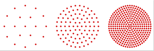
The effect of the Radial distribution setting on the resulting ray placement is illustrated in
Figure 8-2. For
Uniform radius intervals, the distances between the concentric rings of rays are all equal, but the number density of rays is greater at the center of the distribution than at the outer edge. The option
Uniform number density corrects this imbalance by defining nonuniform increments in the radial position between the concentric rings.
Enter a positive integer for the Number of angles 
(dimensionless). The default is
10.
For Hexapolar, enter coordinates for the
Center location qc (SI unit: m). By default, the distribution is centered at the origin. Then enter the components of the
Cylinder axis direction rc (dimensionless). The rays will be released at specified radial distances and angles in the plane containing the point
qc and orthogonal to the direction
rc.
Enter a value or expression for the Radius Rc (SI unit: m). The default is
1 m. Then enter a positive integer for the
Number of radial positions Nc (dimensionless). The default is
5.
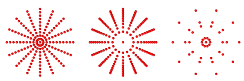
Unlike the Cylindrical grid types described in the previous section, each concentric ring of the
Hexapolar grid releases a different number of rays, as shown in
Figure 8-3. One ray is always released at the center. The first ring of rays surrounding the center has 6 rays arranged in a regular hexagon. Each ring of rays beyond the first has 6 more rays than the ring preceding it, with the grid points arranged in a regular polygon. The radius increments between consecutive rings are uniform.
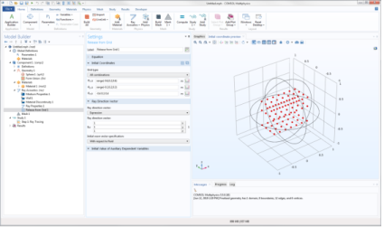
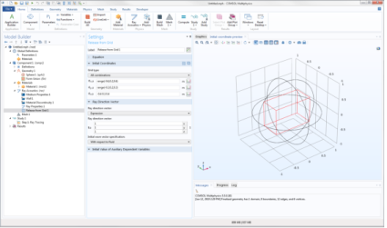
In the Initial Coordinates section, you can click the
Preview Initial Coordinates 
and
Preview Initial Extents 
buttons to visualize the ray release positions. Clicking
Preview Initial Coordinates will cause a point to appear in the Graphics window for every release position. Clicking
Preview Initial Extents will cause a bounding box to appear, indicating the spatial extents of the released rays. Examples are shown in
Figure 8-4 and
Figure 8-5.