•
|
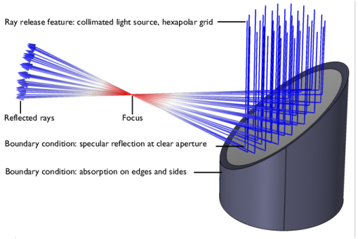
Some rays must be released into the model. This requires at least one ray release feature, such as the Release, Inlet, or Release from Grid node. See Ray Release Features for more details.
|
•
|
Some geometry must be present, with at least one surface that can interact with the rays. Thus, the model must have at least one Boundary condition, such as the Material Discontinuity or Wall node. By default, every boundary adjacent to at least one domain in the model is treated as a Material Discontinuity that can reflect and refract rays. See Boundary Conditions for more information.
|
•
|
Every model includes the Ray Properties node, a default node that cannot be removed. This node defines the equations of ray propagation. If the radiation is monochromatic, this is also where the frequency or wavelength is specified.
|
•
|
The refractive index must be specified. If any domains are present, use the Medium Properties node to either specify the refractive index directly or specify which material controls it.
|
•
|
A study is necessary to compute the ray paths. The Geometrical Optics interface is compatible with the Time Dependent, Ray Tracing, and Bidirectionally Coupled Ray Tracing study steps. Ray Tracing is recommended for most models. See Analysis Types for more information.
|