The Settings window for
Material (

) summarizes the predefined or user-defined material properties for a material. This is where you can add or change material properties to fit your model and assign the material to all types of geometric entities: domains (most common), boundaries, edges (3D models only), or points. Also see
Material Link and
Switch for Materials.
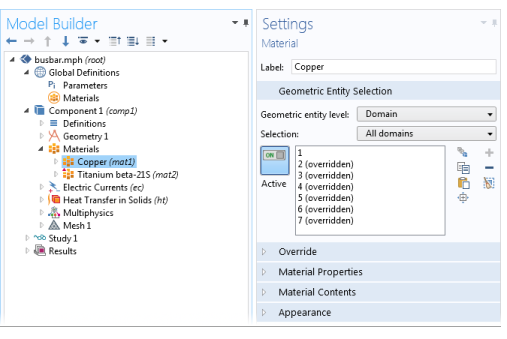
After adding a material (see The Add Material Window and
The Material Browser Window), click the Material node (for example,
Material 1 or
Copper) in the
Model Builder. The
Settings window for
Material opens.
Assign the material to some or all entities on a specific Geometric entity level —
Domain,
Boundary,
Edge (3D only), or
Point — on the geometry in the
Graphics window (the geometry in the model).
The Overridden by list shows the names of the materials that override this material. The
Selection list in the
Geometric Entity section displays
(overridden) for the geometric entities in which this material is overridden.
The Overrides list shows the names of the materials that this material overrides.
You can add material properties to the material if they are not already included. To do so, browse the available material property categories (Basic Properties,
Acoustics, and so on), and select a material property or a collection of material properties in one of the property groups or material models that appear under the main level of material property categories. Right-click the material property or property group and select
Add to Material, or click the
Add to Material button (

) to add the material property or group of properties to the material.
For example, under Acoustics>Viscous Model select
Bulk viscosity (muB) and right-click to
Add to Material or click the
Add to Material button (

). If you add a material model like the
Viscous Model with more than one property, all of its material properties are added to the
Material Contents table. In this example, a
Viscous model node is added to the
Model Builder and its associated properties are added to the
Material Contents table.
The Material type setting decides how materials behave and how material properties are interpreted when the mesh is deformed. Select
Solid for materials whose properties change as functions of material strain, material orientation, and other variables evaluated in a material reference configuration (material frame). Select
Nonsolid for materials whose properties are defined only as functions of the current local state at each point in the spatial frame and for which no unique material reference configuration can be defined.
Simply put, Solid materials associate material properties with specific pieces of the material, and the properties follow the material as it moves around. In particular, a solid material may be inherently anisotropic, meaning that its axes rotate together with the material. The
Nonsolid choice, in contrast, applies typically to liquids and gases whose properties are associated with fixed points in space and insensitive to local rotation of the material. Such materials are inherently isotropic when studied in isolation, but may exhibit anisotropy induced by external fields. In practice, this means that any anisotropic tensor properties in a Non-solid material must be functions of some external vector field.
This section lists all of the material properties that are defined for the material or required by the physics in the model. The table lists the Property,
Variable,
Value, and
Unit for the material property as well as the
Property group to which the material property belongs. The
Property group corresponds to the subnodes in the
Model Builder with the same name. If required, edit the values or expression for the property’s
Value.
You can change the value for any property by editing its value directly in the Value column, or, for a selected property, click the
Edit button (

) to enter a value in the window that opens. If the property can be anisotropic, you can choose to enter the values in one of these forms:
Isotropic,
Diagonal,
Symmetric, or
Anisotropic. The
Variable column lists the variable names corresponding to the degree of anisotropy. For example, for a symmetric electrical conductivity, it contains
{sigma11, sigma12, sigma22, sigma13, sigma23, sigma 33}; sigmaij = sigmaji. For an isotropic electrical conductivity, it contains
sigma_iso; sigmaii = sigma_iso, sigmaij = 0, where
sigma_iso is the name of the variable for the isotropic electrical conductivity (available as, for example,
mat1.def.sigma_iso).
The Family list provides quick settings approximating the appearance of a number of common materials —
Air,
Aluminum,
Brick,
Concrete,
Copper,
Gold,
Iron,
Lead,
Magnesium,
Plastic,
Steel,
Titanium, and
Water. Select
Custom to make further adjustments of the specific settings for colors, texture, reflectance, and so on. The default custom settings are inherited from the material selected last from the
Family list.
For each of these properties, click the Color button to assign a
Custom specular color or select a standard color from the list:
Black,
Blue,
Cyan,
Gray,
Green,
Magenta,
Red,
White, or
Yellow.
The combination of Specular color,
Diffuse color, and
Ambient color gives a 3D object its overall color:
The Noise check box is selected by default, with the default
Normal vector noise scale and
Normal vector noise frequency taken from the material. Enter other values as needed, or click to clear the
Noise check box.
The default Lighting model —
Blinn-Phong or
Cook-Torrance — is based on the material. Select
Simple instead as needed.
For Blinn-Phong, the default
Specular exponent is 64. The specular exponent determines the size of the specular highlight. Typical values for this property range from 1 to 500, with normal objects having values in the range 5 to 20. This model is particularly useful for representing shiny materials.
For Cook-Torrance, the default
Reflectance at normal incidence and
Surface roughness are taken from the material. The Cook-Torrance lighting model accounts for wavelength and color shifting and is a general model for rough surfaces. It is targeted at metals and plastics, although it can also represent many other materials.