Use a Rotated System (

) to define rotation about the out-of-plane axis in 2D and Euler angles in 3D.
In the Settings window for
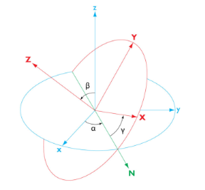
Rotated System define the rotation of the system axes relative to the global Cartesian coordinate system. In 3D models, you orient the rotated system axes (denoted
X,
Y and
Z in
Figure 5-4) using three consecutive Euler angles
α,
β, and
γ, using a
Z-X-Z convention.
The transformation matrix defined by the Euler angles transforms components of a fixed vector v from the rotated coordinate system,
[vX,vY,vZ], to components in the global system,
[vx,vy,vz], as follows:
If this coordinate system is added as a subnode to a Combined System node, define where it will be active using a selection in the
Geometric Entity Selection section. Also, the
Name and
Coordinate names fields are not available in this case.
In the Coordinate names table, the default names are entered —
x1,
x2, and
x3. In planar 2D models,
x1 and
x2 are typically the in-plane coordinates, and
x3 is the out-of-plane coordinate.
For 2D models, select an out-of-plane axis from the Out-of-plane axis list (first, second, or third coordinate direction into or out-of screen). The
Base vectors table updates to reflect the new reference orientation of the in-plane axes. Enter a
Rotation about out-of-plane axis (in radians) to rotate the system relative to the new base vectors, in a counterclockwise direction about the chosen out-of-plane axis. The default rotation is 0.
For 3D models, enter the Euler angles (Z-X-Z) (in radians) in the
α,
β, and
γ fields (see the graphics in the
Settings window for definitions of these angles). The default values are 0 for all angles.
From the Work plane list, select
xy-plane (the default, for a standard global Cartesian coordinate system) or select any work plane in the geometry sequence. If you choose a work plane, the work plane’s coordinates
xw,
yw, and
zw are used for the definition of the rotated system.
