Lumped Parameters
Lumped parameters are matrices describing electromagnetic properties such as resistance, capacitance, and inductance. In the time-harmonic case the lumped parameter matrix is either an impedance matrix or an admittance matrix depending on how the model is excited (current or voltage). In a static calculation only the resistive, capacitive, or inductive part of the lumped parameter matrix is obtained.
Calculating Lumped Parameters with Ohm’s Law
To calculate the lumped parameters, there must be at least two electrodes in the system, one of which must be grounded. Either a voltage or a current can be forced on the electrodes. After the simulation, extract the other property or the energy and use it when calculating the lumped parameter.
There are several available techniques to extract the lumped parameters. Which one to use depends on the physics interface, the parameter of interest, and how the model is solved. The overview of the techniques in this section use a 4-by-4 matrix example for the lumped parameter matrix. This represents a system of at least five electrodes, where four are used as terminals and the rest are grounded, as illustrated in Figure 2-1.
Figure 2-1: A five-electrode system with 4 terminals and one ground electrode.
If a system specifies that all electrodes are terminals, the results are redundant matrix elements. This is better understood by considering a two-electrode system. If both electrodes are declared as terminals, a 2-by-2 matrix is obtained for the system. This is clearly too many elements because there is only one unique lumped parameter between the terminals. If in addition one or more ground electrodes are declared, the system has three unique electrodes and the lumped parameter matrix becomes a 2-by-2 matrix.
Forced Voltage
If voltages are applied to the terminals, the extracted currents represent elements in the admittance matrix, Y. This matrix determines the relation between the applied voltages and the corresponding currents with the formula
so when V1 is nonzero and all other voltages are zero, the vector I is proportional to the first column of Y.
In electrostatics the current is replaced with charge and the admittance matrix is replaced with the capacitance matrix
Fixed Current
It might be necessary to calculate the Z-matrix in a more direct way. Similar to the Y calculation, the Z calculation can be done by forcing the current through one terminal at the time to a nonzero value while the others are set to zero. Then, the columns of the impedance matrix are proportional to the voltage values on all terminals:
Fixed Charge
The Electrostatics interface can use total charge instead of total current. This gives the inverted capacitance matrix in a similar manner as the Z and Y matrices.
Calculating Lumped Parameters Using the Energy Method
When using this method the potential or the current is nonzero on one or two terminals at a time and the energy density is extracted and integrated over the whole geometry. The following formulas show how to calculate the capacitance matrix from the integral of the electric energy density.
S-Parameters
Scattering parameters (or S-parameters) are complex-valued, frequency-dependent matrices describing the transmission and reflection of electromagnetic waves at different ports of devices like filters, antennas, waveguide transitions, and transmission lines. S-parameters originate from transmission-line theory and are defined in terms of transmitted and reflected voltage waves. All ports are assumed to be connected to matched loads/feeds, that is, there is no reflection directly at a port.
For a device with n ports, the S-parameters are
where S11 is the voltage reflection coefficient at port 1, S21 is the voltage transmission coefficient from port 1 to port 2, and so on. The time average power reflection/transmission coefficients are obtained as | Sij |2.
Now, for high-frequency problems, voltage is not a well-defined entity, and it is necessary to define the scattering parameters in terms of the electric field.
S-Parameter Calculations
The MEMS interfaces have built-in support for S-parameter calculations. In the Electric Currents and Electrostatics interfaces, use the terminal boundary feature with the 
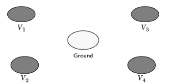
terminated setting to approximate a connecting transmission line or a voltage source with a known internal impedance. For a terminal the voltage measurement is always with respect to ground so at least one ground feature is also required in the model.
S-Parameter Variables
This module automatically generates variables for the S-parameters. The port names (use numbers for sweeps to work correctly) determine the variable names. If, for example, there are two ports with the numbers 1 and 2 and Port 1 is the inport, the software generates the variables S11 and S21. S11 is the S-parameter for the reflected wave and S21 is the S-parameter for the transmitted wave. For convenience, two variables for the S-parameters on a dB scale, S11dB and S21dB, are also defined using the following relation:
The model and physics interface names also appear in front of the variable names so they can vary. The S-parameter variables are added to the predefined quantities in appropriate plot lists.
Port/Terminal Sweeps and Touchstone Export
The, Manual Terminal Sweep Settings section in the Electrostatics interface and the Manual Terminal Sweep Settings section in the Electric Currents interface describe how to cycle through the terminals, compute the entire S-matrix and export it to a Touchstone file.
Lumped Parameter Conversion
When the impedance matrix, Z, or the admittance matrix, Y, is available it is possible to calculate all other types of lumped parameter matrices from the relations below.
where L is the inductance, C is the capacitance, R is the resistance, and G is the conductance. S is the S-parameter. The relations also include the following matrices
where Z0 is the characteristic impedance.
You can compute conversions between the impedance matrix, Z, the admittance matrix, Y, and the S-parameter matrix S in a results table using the Settings window for the Global Matrix Evaluation node, which you can add under Results>Derived Values.
Global Matrix Evaluation in the COMSOL Multiphysics Reference Manual