Table 6-4: Graphics Toolbar Buttons by Space Dimension
|
|
|
|
|
|
|
|
|
|
|
|
|
|
|
|
|
|
|
|
|
|
|
|
|
|
|
|
||
|
|
|||
|
|
|
|
|
|
|
|||
|
|
|||
|
|
|||
|
|
|||
|
|
|||
|
|
|
||
|
|
|
|
|
|
|
|||
|
|
|||
|
|
|||
|
|
|
||
|
|
|||
|
|
|||
|
|
||
|
|
||
|
|
||
|
|
||
|
|
||
|
|
||
|
|
||
|
|
||
|
|
||
|
|
||
|
|
||
|
|
||
|
|
||
|
|
|
3D only: Click the middle mouse button and drag it forward and backward to zoom in and out of the object. The zoom is centered where the first click is made in the Graphics window.
|
||
|
|
To zoom into a general area of the geometry, click the Zoom Box button then click and drag to highlight a section of the geometry to zoom into.
|
|
|
|
Click the Zoom to Selection button to zoom into the selected geometric entities. This button is also available in connection with the selection lists for domains, boundaries, edges, and points. This zoom operation also updates the center of rotation, which will stay active until you click the Zoom Extents or the Go to Default 3D View button to reset it.
|
|
|
|
Click the Zoom Extents button to zoom out and fit the complete geometry into the window.
|
|
|
Click the Go to XY View, Go to YZ View, and Go to ZX View buttons to change the view to the xy-, yz-, or zx-plane. The first click selects the plane view with a positive normal direction. A second click on the same button switches to a negative normal direction. A third click flips the direction in the plane, and a fourth click switches the normal again, so the clicks cycle through all four possible views for the chosen plane.
|
|
|
|
Click the Go to Default View button to change the view to the default view.
|
|
|
After creating a View under the Definitions node, click the down arrow next to the Go to View button (
|
||
|
|
Click the Show Axis Orientation button to toggle the display of the axis orientation indicator (triad) in the lower-left corner of the 3D Graphics window on or off.
|
|
|
|
Click the Show Grid button to toggle the display the grid box on or off in the 2D and 3D Graphics window.
|
|
|
|
Click the Show Legends button to toggle the display of the color legend and color scale on or off in 2D and 3D Graphics windows or to toggle the display of legends on or off in 1D Graphics windows.
|
|
In the Graphics window, left-click and hold down the mouse button while dragging it in any direction.
|
||
|
In the Graphics window, right-click and hold down the mouse button while dragging it in any direction.
|
||
|
In the Graphics window, click and hold down the middle mouse button and drag the mouse forward or back to zoom in and out.
|
||
|
Press Ctrl and left-click in the Graphics window. While holding down the key and button, drag the mouse in any direction.
|
||
|
Press Ctrl and right-click in the Graphics window. While holding down the key and button, drag the mouse in any direction.
|
||
|
Press Ctrl+Alt, then left-click in the Graphics window. While holding down the keys and button, drag the mouse in any direction. If you have not rotated the camera (using Ctrl+left-click), the effect is the same as when using Alt+left-click.
|
||
|
Press Alt, then right-click the mouse in the Graphics window. While holding down the key and button, drag the mouse in any direction.
|
||
|
Press Ctrl and then click the middle mouse button. While holding down both the key and button, in the Graphics window, drag the mouse in any direction.
|
||
|
Press Alt, then left-click in the Graphics window. While holding down the key and button, drag the mouse in any direction.
|
||
|
Press Alt, then middle-click in the Graphics window. While holding down the key and button, drag the mouse in any direction.
|
|
|
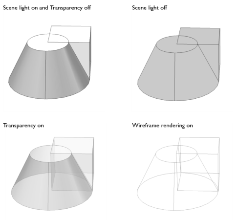
Click any plot under Results. In the Graphics window or any other plot window, click the Scene Light button to turn it on. Click again to turn scene light off. See Figure 6-10.
|
|
|
|
Click any plot under Results. In the Graphics window or any other plot window, click the Transparency button to turn it on. Click again to turn transparency off. See Figure 6-10.
When creating a View, this action toggles the Transparency check box on the View page. See User-Defined Views.
|
|
|
|
Click any plot under Results. In the Graphics window, click the Wireframe Rendering button to turn it on. Click again to turn the wireframe off. See Figure 6-10. Note that wireframe rendering only has effect when mesh rendering is turned off (for a view that normally shows the mesh).
When creating a View, this action toggles the Wireframe rendering check box on the View page. See User-Defined Views.
See also Preferences Settings to set the level of graphic detail to Wireframe and speed up the rendering of complex models or to improve visual appearance.
|
|
|
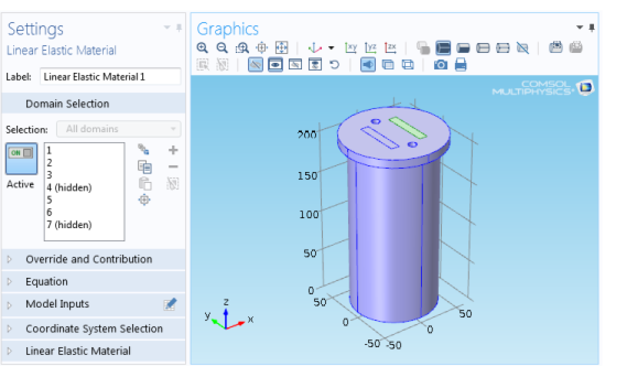
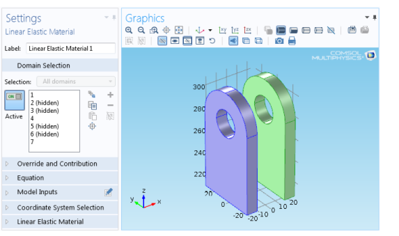
In the Graphics window, toggle the Click and Hide button (click to highlight and turn on and click again to turn off). When turned on, click on a geometric entity or geometry object, and it is then hidden and added to the list of hidden entities or hidden geometries in the Hide for Geometry or Hide for Physics node under a View. In the Selection lists, (hidden) appears next to the entity number. When click and hide is active, the cursor changes to indicate that clicking now hides objects:
When creating a View, right-click the View node and select Hide for Geometry or Hide for Physics, depending on the current node in the model tree. Select a Geometric entity level from the list to hide.
|
|||||
|
|
In the Graphics window, click the View Unhidden button to display any geometry objects, domains, boundaries, edges, or points not hidden.
|
|||||
|
|
In the Graphics window, click the View Hidden Only button to display only hidden geometry objects, domains, boundaries, edges, or points.
|
|||||
|
|
In the Graphics window, click the View All button to display all hidden and unhidden geometry objects, domains, boundaries, edges, or points.
|
|||||
|
|
In the Graphics window, click the Reset Hiding button to reset all hidden geometry objects, domains, boundaries, edges, or points to the default.
This removes any Hide for Geometry or Hide for Physics subnodes added to a View node (when in geometry mode, Hide for Physics subnodes are not removed).
|
|
|
When the View Hidden Only button (
|