Stiffness
The connection between the two boundaries is modeled using a spring matrix with stiffness properties designed to replicate the flexibility introduced when two holes are connected by a fastener. The displacements at the two ends of the fastener are represented by the average displacement of each corresponding hole.
For the Shell interface, the displacement is taken on the plate side defined by a connected location. This side can be determined automatically or specified by the user. In either case, the key assumption is that there is no offset in the direction of the shell normal between the measurement points. In other words:
The stiffness in the normal direction, kn, is a given by the axial stiffness of a bar
Here, Ef is the fastener Young’s modulus and df is the fastener diameter. The total length is the sum of the thickness of the plate on the destination side, tdst, and the thickness on the source side, tsrc.
In the Solid Mechanics interface, the Fastener node can be used to model a pretensioned bolt connection. To account for this, the effective length of the fastener includes an estimated bolt head thickness. The normal stiffness then becomes
The stiffness in the transverse direction, ks, is more complicated. There are several contributions to the deformation of the rivet-plate system. Four compliance terms connected in series are considered,
Here, Cb is the fastener bending flexibility, Cs is the fastener shear flexibility, Cbr is the fastener bearing flexibility, and Cpbr is the plate bearing flexibility.
The compliance contributions are defined as
In these expressions
Esrc and Edst are the elastic moduli of the shell on the source and destination sides, respectively.
Ef, νf, and df are the fastener stiffness, Poisson’s ratio, and diameter, respectively.
tsrc and tdst are the thickness of the plate on the source and destination sides, respectively.
The multipliers αm make it possible to adjust the analytical expressions.
In case of a pretension load, the clamped plates transfer a large part of the applied load. This partitioning of the load is a function of the relative stiffness of the bolt and the joint members. With an increment in the external load, ΔFext, then
Here, ΔFn is the change in load carried by the bolt, and ΔFg is the change in the load carried by the plates. The joint constant, Cj, is defined as
where kg is the called grip stiffness, explained below.
As opposed to when using a full bolt pretension study, the fasteners offer a simplified approach where there is no special study step for computing the preloaded case. Rather, an analytical approximation to the state after preload is used.
In the following, un is the displacement in the normal direction between the plates, measured positive when the fastener is extended, so that the increment in the fastener force is
Now, assume a preload, Fpre. After pretensioning the bolt, there is no resulting external force. The preload in the fastener is balanced by the stress in the surrounding plates. That is
The connection will be compressed a distance un0, which is negative. The force in the joint members is compressive,
which provides a value for Δun0. It is now possible to write the expression for the total fastener force under an arbitrary extension as
The fastener normal force can thus be expressed in a compact way as
To approximate the grip stiffness, the following approach is used. The pressure distribution through the thickness of the grip is approximated by a conical shape, also called frustum. The total grip stiffness is a combination of the frustum stiffnesses as described below
When the connected plates have the same thickness, two frustums are considered as shown in the figure below
Figure 3-46: Conical pressure profile for two plates of the same thickness.
For each frustum, the stiffness is estimated using Shigley’s method as expressed by
When the plates do not have the same thickness, a third frustum is introduced as shown in the figure below
Figure 3-47: Conical pressure profiles for plates of different thicknesses.
For each frustum, the stiffness is defined by
with the thicknesses defined as of the thinnest plate, and
and
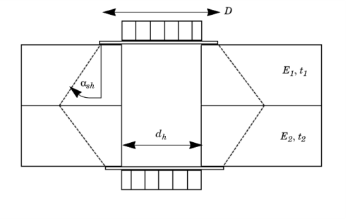
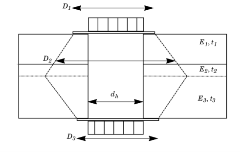
The grip stiffness is approximated by giving a value for the frustum angle αsh, which can also depend on the material, the thickness of the plates, and the applied external load.
The displacement difference is defined using the average hole displacement on the two sides:
Using the normal to the shell on the destination side, n, the displacement difference can be separated into normal and tangential parts:
The contribution to the virtual work for the fastener is then
In presence of a pretension load, the contribution become