The orientation of a piezoelectric crystal cut is frequently defined by the system introduced by the IRE standard of 1949 (Ref. 8). This standard has undergone a number of subsequent revisions, with the final revision being the IEEE standard of 1987 (
Ref. 9). Unfortunately, the 1987 standard contained a number of serious errors and the IEEE subsequently withdrew it. COMSOL therefore adopts the preceding 1978 standard (
Ref. 10), which is similar to the 1987 standard, for material property definitions. Most of the material properties in the material library are based on the values given in the book by Auld (
Ref. 11), which uses the 1978 IEEE conventions. This is consistent with general practice except in the specific case of quartz, where it is more common to use the 1949 IRE standard to define the material properties. COMSOL therefore provides additional sets of material properties consistent with this standard for the case of quartz. Note that the material properties for quartz are based on
Ref. 12, which uses the 1949 IRE standard (the properties are appropriately modified according to the different standards).
The stiffness, compliance, coupling, and dielectric material property matrices are defined with the crystal axes aligned with the local coordinate axes. Note that the signs of several matrix components differ between the 1949 and the 1978 standards (see Table 2-10). In the absence of a user-defined coordinate system, the local system corresponds to the global
X,
Y, and
Z coordinate axes. When an alternative coordinate system is selected this system defines the orientation of the crystal axes. This is the mechanism used in COMSOL to define a particular crystal cut, and typically it is necessary to calculate the appropriate Euler angles for the cut (given the thickness orientation for the wafer). All piezoelectric material properties are defined using the Voigt form of the abbreviated subscript notation, which is universally employed in the literature (this differs from the standard notation used for the Solid Mechanics interface material properties). The material properties are defined in the material frame, so that if the solid rotates during deformation the material properties rotate with the solid. See
Modeling Geometric Nonlinearity.
Crystal cuts are usually defined by a mechanism introduced by the IEEE/IRE standards. Both standards use a notation that defines the orientation of a virtual slice (the plate) through the crystal. The crystal axes are denoted X,
Y, and
Z and the plate, which is usually rectangular, is defined as having sides
l,
w, and
t (length, width, and thickness). Initially the plate is aligned with respect to the crystal axes and then up to three rotations are defined, using a right-handed convention about axes embedded along the
l,
w, and
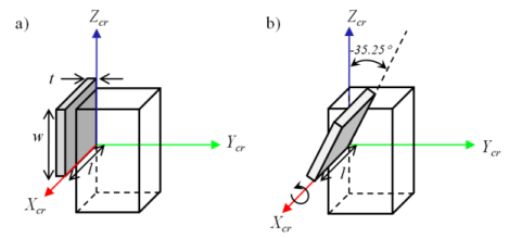
t sides of the plate. Taking AT cut quartz as an example, the IEEE 1978 standard defines the cut as: (
YXl)
−35.25°. The first two letters in the bracketed expression always refer to the initial orientation of the thickness and the length of the plate. Subsequent bracketed letters then define up to three rotational axes, which move with the plate as it is rotated. Angles of rotation about these axes are specified after the bracketed expression in the order of the letters, using a right-handed convention. For AT cut quartz only one rotation, about the
l axis, is required. This is illustrated in
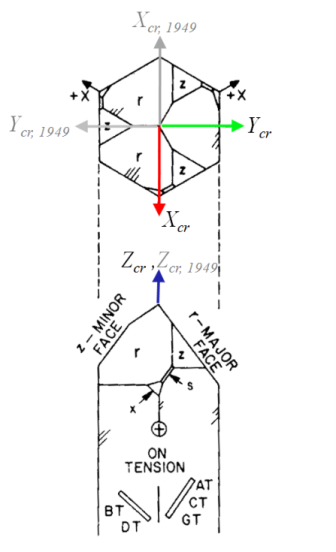
Figure 2-20. Note that within the 1949 IRE Standard AT cut quartz is denoted as: (
YXl)
+35.25°, since the
X-axis is rotated by 180° in this convention and positive angles therefore correspond to the opposite direction of rotation (see
Figure 2-19).
Table 2-11 summarizes the differences between the standards for different crystal cuts.
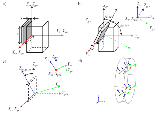
When defining the material orientation, it is necessary to consider the orientation of the plate with respect to the global coordinate system in addition to the orientation of the plate with respect to the crystallographic axes. Consider the example of AT cut quartz in Figure 2-20. The definition of the appropriate local coordinate system depends on the desired final orientation of the plate in the global coordinate system. One way to set up the plate is to orient its normal parallel to the
Y-axis in the global coordinate system.
Figure 2-21 shows how to define the local coordinate system in this case.
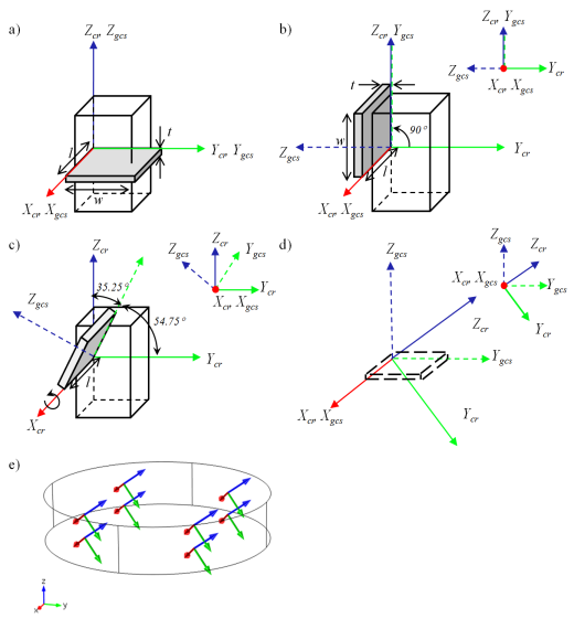
Figure 2-22 shows how to define the local system such that the plate has its normal parallel to the global
Z-axis. In both cases it is critical to keep track of the orientation of the local system with respect to the global system, which is defined depending on the desired orientation of the plate in the model.
There are also a number of methods to define the local coordinate system with respect to the global system. Usually, it is most convenient to define the local coordinates with a Rotated System node, which defines three Euler angles according to the ZXZ convention (rotation about
Z, then
X, then
Z again). Note that these Euler angles define the local (crystal) axes with respect to the global axes — this is distinct from the approach of defining the cut (global) axes with respect to the crystal (local) axes.