Solid Mechanics (solid)
If you expand the Solid Mechanics (solid) node, you can see that a Continuity node has been automatically added.
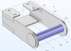
This means that the flanges of the pin will be bonded to the bracket arms. Since the boundaries of the pin are geometrically adjacent to the bracket, this was automatically identified. You can check, and, if needed, modify the definition of a pair under the Definitions branch in the Model Builder window.
Linear Elastic Material 1: Adding Initial Stress and Strain
The initial strain is specified under the Linear Elastic Material node.
1
In the Model Builder window, under Solid Mechanics (solid), click Linear Elastic Material 1. In the Physics toolbar click Attributes
and select Initial Stress and Strain
.
As an alternative, you can right-click on the Linear Elastic Material 1 node, and select Initial Stress and Strain from the context menu.
2
In the Settings window for Initial Stress and Strain, locate the Domain Selection section. From the Selection list, choose Manual.
3
To the right of the Selection list, click the Clear Selection button
. Then select only Domain
2
(the pin).
The prestrain direction is the axial direction of the pin, which coincides with the global
x
direction.
4
Under the Initial Stress and Strain section, enter
InitStrain
in the first component of the
ε
0
table.