Definitions — Local Coordinate System
The reference orientation of the coordinate system used to describe the load distribution must now be changed, so that the reference orientation is aligned with the
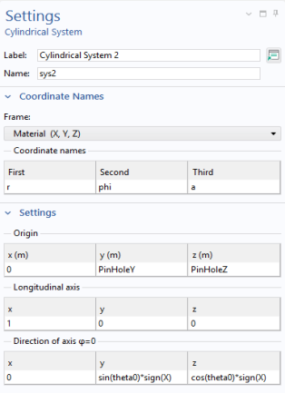
Cylindrical System 2 (sys2)
1
In the Model Builder window, expand the Component 1 and Component 1 > Definitions nodes, then click Cylindrical System 2 (sys2).
2
In the Settings window for Cylindrical System, locate the Settings section.
3
Find the Direction of axis
φ
=0 subsection. In the table, enter the following settings:
x
y
z
0
sin(theta0)
cos(theta0)
The orientation of the coordinate system now depends on the parameter theta0.
Since the load now is rotating in the hole, it is no longer sufficient that half of the holes are selected.
Left Pin Hole
1
In the Model Builder window, expand the Component 1 (comp1) > Definitions > Selections node, then click Left Pin Hole.
2
In the Settings window for Explicit, locate the Input Entities section. Select the Group by continuous tangent checkbox.
Right Pin Hole
3
Select the Right Pin Hole node, and make the same change.