Mesh 1
Start by creating an edge mesh around the bolt holes to make sure that they are properly resolved.
Edge 1
1
2
Distribution 1
1
2
Create a mesh that is swept through the thin flat parts, and then use a free tetrahedral mesh in the parts with a more complex geometry. Note that the transition between the two types of elements is automatic. A layer of pyramid elements will be generated there.
Swept 1
1
2
Size 1
1
2
3
4
You are going to use the element size later in the modeling. It is then a good idea to convert it into a parameter. It is possible to add new parameters on the fly from any input field that supports parameters. You can right-click in an empty text field to do that, but you can also convert an existing value into a parameter.
5
6
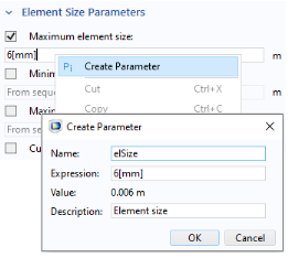
In the Create Parameter dialog, type elSize in the Name text field, and Element size in the Description text field.
7
The value in the expression for the element size is now automatically substituted by the new parameter name.
The parameter was added to the list in the Parameters 1 node, and can later be modified there if necessary. You can also select any parameter in a text field, right-click it, and immediately modify its value or description.
Size
1
2
3
Free Tetrahedral 1
1
The default selection is Remaining, that is all not yet meshed domains.
Size 1
1
2
3
4
5
Select the Maximum element size checkbox. In the associated text field, type elSize. In a case where you did not remember the exact name, you could, for example, type just ā€˜e’ and then Ctrl-Space to get a list of suggestions.
Size 2
Use a finer mesh in the fillets where high stresses can be anticipated.
1
2
3
4
You should now have a mesh which looks similar to this:
displaying physics symbols in the graphics window
When working with the physics features, the current selection is shown in the Graphics window. You can add symbols to describe the type of boundary condition applied to the selection.
The symbols indicate only the type of settings applied to the model and not the actual magnitude or direction. If you are interested in visualizing an actual applied load, a solution must be computed first.
You turn the physics symbols on by selecting Enable physics symbols in the settings for a physics interface.
When physics symbols are enabled for the interface, a Physics Symbols section will be shown in the settings for each node in the Model Builder tree that has an associated symbol. You can then control the state of the physics symbols for individual boundary conditions.
You can click the Wireframe Rendering button to see the symbols everywhere.