Definitions - Selections
Regardless of whether the geometry is treated as a single entity or as an assembly, you still may need to access different parts of it for definitions, such as multiple specifications of similar boundary conditions. There are different ways in which you can create selections, for example by explicit selection of objects or by geometrical location. A box selection is independent of the geometry, and allows you to change the geometry topology while still keeping the desired selection.
In this example, one selection contains the bolt regions, while other selections contain the boundaries of the pin holes that carry load.
Bolt 1
1
2
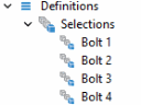
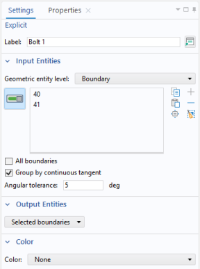
In the Settings window for Explicit, in the Label text field, type Bolt 1. You can also click any node in the model builder tree and press F2 to rename, or right-click and select Rename.
3
4
5
6
Select the Group by continuous tangent checkbox. Boundary 40 is automatically added to the selection list.
Bolt 2, Bolt 3, and Bolt 4
Repeat the steps completed for Explicit 1 to add a total of four Explicit nodes .
1
2
3
The node sequence under Definitions should look like this at this point:
You will now create a selection containing all the bolt holes.
Bolt Holes
1
2
3
4
5
6
7
Note: This assumes default settings for color themes.
Now, create selections for the two holes carrying the load.
Left Pin Hole
1
2
3
4
5
Right Pin Hole
Repeat the steps above, but use the label Right Pin Hole, select Boundary 75, and use the second color in the second row (a light brown color) on Windows platform, or choose Color 12 on other platforms. Now the sequence under Definitions should look like this:
Pin Holes
Add a selection that combines the pin hole boundaries on both sides.
1
2
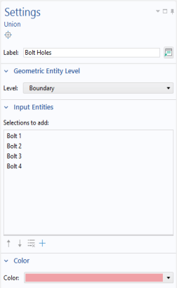
In the Settings window for Union, type Pin Holes in the Label text field.
3
4
5
6
Bolt Hole Edges
Add one more selection to be used during mesh generation.
1
2
3
4
5
6
7
8
Centroid Measurement 1
As a preparation for adding load in the pin holes you will add a local coordinate system. Start by finding the location of the pin hole center line. You can directly create parameters for the coordinates that can be referenced in other nodes.
1
2
3
4
Then type PinHoleY and PinHoleZ, in the y and z text field respectively.
5
Cylindrical System 2
Since the load in the pin holes has a dependence on the angle, it is convenient to use a cylindrical coordinate system aligned with the pin to express the load.
1
2
3
Note how two cylindrical systems with different reference orientations are created by making the orientation of the reference axis dependent on in which arm the system is referenced. This can be done by using the sign of the X-coordinate.