|
1
|
|
5
|
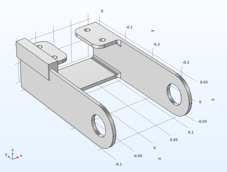
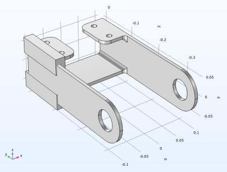
Browse to the folder Structural_Mechanics_Module\Tutorials under the COMSOL installation directory and double-click the file bracket.mphbin.
|
|
4
|
|
16
|
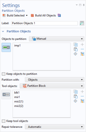
Locate the Normal Vector to Plane of Reflection section. In the x text field, type 1. In the z text field, type 0.
|