The Fundamentals: A Static Linear Analysis
This section summarizes the fundamentals for modeling structural mechanics problems and applying them in COMSOL Multiphysics and the Structural Mechanics Module. It includes instructions for creating a geometry, generating a mesh, defining material properties, and imposing boundary conditions. After the solution is computed, you will learn how to display and analyze the results.
The model used in this guide is an assembly of a bracket and its mounting bolts, which are all made of steel. This type of bracket can be used to install an actuator that is mounted on a pin placed between the two holes in the bracket arms. The geometry and the loading are shown in Figure 8.
Figure 8: The geometry of the bracket together with the load distribution.
In this initial analysis, the mounting bolts are assumed to be fixed and securely bonded to the bracket, so they will be replaced by boundary conditions at the bolt holes. To model the external load from the pin, specify a surface pressure p with a trigonometric distribution on the inner surfaces of the two holes, given by
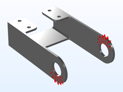
where p0 is the peak load intensity, and α is the angle from the direction of the load resultant. This is a common assumption for pins with a small clearance. One of the arms is loaded upward, and the other downward. The resultant load in each hole is Fh = 800 N. The pressure intensity p0 can be determined from an integration of the projected pressure
where t is the thickness of the arm, and d is the diameter of the hole.
This example contains several steps that are not strictly necessary for the task. Rather, they are intended to showcase useful functionality. Examples of this are the coloring of various selections, addition of certain plots, and so on.