Mesh 1
We will use a user-defined mesh for this model.
1
In the Model Builder window, under Component 1 (comp1) click Mesh 1
.
2
In the Settings window for Mesh, locate the Mesh Settings section. From the “Sequence type” list, choose User-controlled mesh.
Size
1
In the Model Builder window, under Component 1 (comp1) > Mesh 1 click Size
.
2
In the Settings window for Size, locate the Element Size section. Click the Custom button.
3
Locate the Element Size Parameters section. In the “Maximum element growth rate” text field, type 1.05.
Size 1, Size 2 and Free Triangular 1
1
In the Model Builder window, under Component 1 (comp1) > Mesh 1 right-click Size 1
and choose Delete. In the Confirm Delete pop-up window, click Delete.
2
Right-click Size 2
and choose Delete. In the Confirm Delete pop-up window, click Delete.
3
Right-click Free Triangular 1
and choose Delete. In the Confirm Delete pop-up window, click Delete.
Edge 1
1
Right-click Mesh 1 and choose Edge
.
2
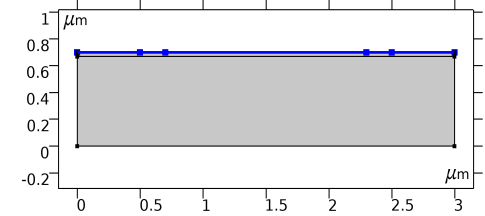
In the Settings window for Edge, locate the “Boundary Selection” section. Select Boundaries 3–7 only (the top surface of the device).
3
Click to expand the “Control Entities” section. Clear the “Smooth across removed control entities” checkbox.
Size 1
1
Right-click Edge 1 and choose Size
.
2
In the Settings window for Size, locate the Element Size section.
-
From the “Calibrate for” list, choose Semiconductor.
-
Click the Custom button.
3
Locate the Element Size Parameters section.
-
Select the “Maximum element size” checkbox.
-
In the associated text field, type
0.03
.
Mapped 1
1
In the Model Builder window, right-click Mesh 1 and choose Mapped
.
2
In the Settings window for Mapped, locate the Domain Selection section.
-
From the “Geometric entity level” list, choose Domain.
-
Select Domain 2 only.
3
Click to expand the “Control Entities” section. Clear the “Smooth across removed control entities” checkbox.
4
Click to expand the Reduce Element Skewness section. Select the “Adjust edge mesh” checkbox.
Distribution 1
1
Right-click Mapped 1 and choose Distribution
.
2
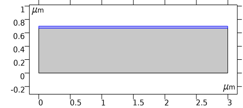
Select Boundary 9 only (use the mouse scroll wheel to cycle through possible selections when multiple ones are within a short distance from the mouse pointer, as in this case)
.
3
In the Settings window for Distribution, locate the Distribution section.
-
From the “Distribution type” list, choose Predefined.
-
In the “Number of elements” text field, type
8
.
-
In the “Element ratio” text field, type
9
.
-
From the “Growth rate” list, choose “Exponential”.
-
Select the “Reverse direction” checkbox.
Free Triangular 1
1
In the Model Builder window, right-click Mesh 1 and choose Free Triangular
.
2
In the Settings window for Free Triangular, click to expand the “Control entities” section. Clear the “Smooth across removed control entities” checkbox.
3
Click Build all
.
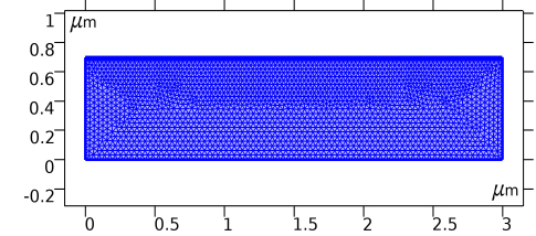
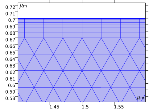
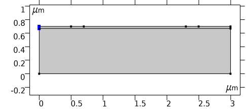
The user-defined mesh is shown in the images below. The mapped mesh with the specific distribution helps create layers of thin elements underneath the gate, where the large gradient of the carrier concentration needs to be resolved by the mesh.
 .
.