Theory for Solid-Bearing Coupling
Coupling of any structural component with the Hydrodynamic Bearing interface requires a correct evaluation of the change in film thickness due to the relative motion of the solid component and bearing surfaces. This relative motion can be split into two components: sliding and squeezing. Sliding motion does not change the film thickness, provided that there is a natural geometrically wedge in which the lubricant is trapped. Squeezing motion, however, directly affects the film thickness. Therefore, the motion of the structural components has to be split into these two components to evaluate the change in the film thickness.
Consider the structure and bearing arrangement shown in Figure 8-1
Figure 8-1: Structure moving in bearing. The initial position of the structure is dashed.
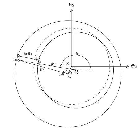
Initially, both structure and bearing are concentric to each other with the common center located at Xc. During operation they move relative to each other. Let the centers of the structure and bearing now be located at xcs and xcb, respectively. The film thickness is obtained by calculating the height of the bearing surfaces from the structure surface. To evaluate the film thickness, consider a radial line from the current center of the structure xcs at an angle Θ from the local y-axis. This line intersects the bearing and the structural surfaces at points B and S, respectively. The radial line from the new center of the bearing xcb to B makes an angle Θb from the local y-axis. Let the normalized radial vectors from structure and bearing surfaces be er(Θ) and er(Θb), respectively. The position vector of the point B is given by
Similarly, the position vector of the point S is given by
Here xb and xs are the position vectors of the points B and S, respectively. Rb(Θb) and Rs(Θ) are the radial positions of the bearing and structure surfaces from their respective centers. Since the points B and S are located along the radial vector er(Θ):
In the local bearing coordinate system:
(8-1)
Here, e1 is the bearing axis direction, and e2 and e3 are the two transverse directions.
Substituting the expressions for xb, xs, er(Θ), er(Θb), and eθ(Θ) in Equation 8-1 and simplifying gives
Since the centers of both the bearing and the structural surfaces were initially at the reference surface center, we have xcb = Xc + ucb and xcs = Xc + ucs. Therefore,
(8-2)
and
Given that
the film thickness can be approximated as
This requires an evaluation of the radial position of the bearing with angular coordinate Θb. If the difference between Θb and Θ is assumed to be small, Equation 8-2 gives:
A Taylor series expansion gives:
This can be generalized to include the change in Rb in the axial direction too in the following way:
Substituting this in the film thickness expression:
If the surface of the structure is flat or cylindrical, the tangential gradient of the radial position on the structure surface will be zero. Using C = RbRs the film thickness is