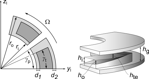
The hatched area in the figure is the tapered area and rest of the area is flat. The flat areas near the inner and outer diameter edges are called the inner and outer dam. The width of the inner and outer dams are d1 and
d2, respectively. The arc angle for the tapered area is denoted
γt ri and
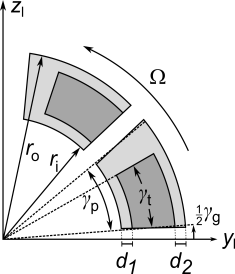
ro are the inner and outer radius of the pad, respectively. Two types of grooves are usually used in the tapered bearings: one in which the groove makes a constant arc angle about the center as shown in the
Figure 7-20 and the second in which the groove is of constant width as shown in
Figure 7-21. On the tapered area, a linear variation of the thickness is assumed.
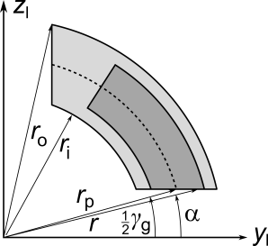
The local y direction in the constant arc groove bearing is considered to be passing through the leading edge of the pad. If the initial clearance at the outer diameter side of the trailing edge is
hte, and the tapered depth on inner and outer diameter side is
hi and
ho, respectively, then the film thickness in the tapered area can be approximated as
where Θit,te is the azimuthal angle of the trailing edge side of the tapered area of the
ith pad from the local
y direction, defined as
where hg is the depth of the groove.
The local y direction is in this case considered to pass from the center of the groove as opposed to the leading edge of the pad in other cases.
In the above expression, r can vary from the inner radius
ri to outer radius
ro. Since the pad depths at trailing edge outer diameter, and the relative depth of the pad from this location to the leading edge outer and inner diameter are known, the film thickness variation in the tapered area can be calculated by assuming a linear variation in radial and circumferential directions:
The thicknesses h0,
hr, and
hθ are yet unknown. They can be determined by the following information: