Tilting Pad Bearing
A tilting pad bearing is a type of thrust bearing in which the oil wedge is created by the natural tilting of the pads due to the lubricant pressure. The tilting of the pad can occur about a radial axis in the line pivot configuration or about both radial and circumferential axis in the point pivot configuration. In addition, tilting of the pads provide the freedom to adjust for the misalignment of the rotor within the bearings. Figure 7-18 and Figure 7-19 show a typical bearing and pad geometry for a tilting pad thrust bearing with line pivot and point pivot configurations, respectively.
Figure 7-18: Geometry of a tilting pad thrust bearing with line pivot configuration.
Figure 7-19: Geometry of a tilting pad thrust bearing with point pivot configuration.
Oil grooves are provided between the pads to supply the lubricant. Therefore, sets of a pad and a groove are repeated in the circumferential direction making the bearing sector symmetric with the sector angle 2π/N, where N is the number of the pads in the bearing. Let us consider a local y direction passing through the leading edge of one of the pads and let rc be the coordinate of the center of the bearing. Then for a point at position r on the bearing pad, its radial and azimuthal coordinates are:
where e2 and e3 are the local directions in the bearing. The first pad on the bearing is then located between
The ith pad will therefore be located between
The groove sector angle can be obtained as
.
The location of the pivot is specified by the circumferential offset, βc, and the radial offset, βr, with
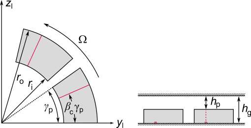
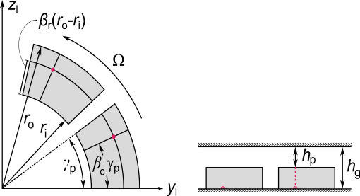
The location of the pivot point for the ith pad from the bearing center is, in polar coordinates, given by
Denote the tilt angles of the ith pad about the radial and circumferential directions by δir and δic, respectively. Assuming that these tilt angles are small, the tilt vector can be written as
where
are the radial and circumferential directions on the ith pad. Due to tilting of the pad, the displacement at a point X on the pad surface is
Here Xip is the position vector of the pivot point of the ith pad with respect to bearing center,
The axial component of the displacement due to the tilting at a point on the pad will change the film thickness at that location, and is given by
If the film thickness at the pivot point is hp then the film thickness due to tilting at a point X on the pad due to tilting will be
where plus sign is used when the pad is along the positive axial direction from the collar surface and negative sign when the pad is along the negative axial direction from the collar surface.
Therefore, the film thickness variation in the ith sector of symmetry is
In this expression for the film thickness, the tilt angles of the pad are unknown. They can be determined by balancing the moment on the pad caused by the pressure distribution. The moment balance on the pad has to be treated differently depending on the study type. For a stationary analysis, inertial effects are ignored, and thus the tilt angles are obtained by setting the net moment on each pad about the pivot point to zero.
The reference surface normal is parallel to the axial direction but the direction of the normal could be either along or opposite to the axial direction. Using this fact, the moment equation reduces to
where a plus sign is used if the reference surface normal is along the axial direction and a negative sign is used otherwise. This approach results in two equations, one along the radial direction and other along the circumferential direction. These equations basically determine the tilts δir and δic, respectively. In the line pivot case, only the radial direction equation is used.
In a time-dependent analysis, the inertia of the pads also plays a role in the tilting motion. Including the pad inertia, the moment balance equations are modified to
For the pad with sector angle γ, inner radius ri, outer radius ro, and thickness tp, and the pivot locations specified as above, the mass moment of inertia components about the pivot point are given by
Spring Loaded Pad
Sometimes instead of pads being freely pivoted, they are mounted on springs. Then the external moment due to pressure distribution in the film is balanced by the spring moment. In the stationary case, this moment balance is
In a time-dependent analysis pad inertia is also included, giving