Tilting Pad
In a tilting pad journal bearing, the bearing surface is described by multiple pads, similar to the multilobe bearings. The difference is that the pads in this case are free to tilt. Tilting of the pad can occur either about an axis parallel to the bearing axis, called a line pivot configuration, or about both axial and circumferential directions of the bearing. The latter is called a point pivot configuration. Therefore, the film thickness in this case is also a function of the pad tilt angle. A sketch of the tilting pad bearing is shown in Figure 7-13:
Figure 7-13: Tilting pad journal bearing.
Figure 7-14: Pad geometry.
As an effect of the loading, the bearing pads tilt by angles δia and δic about the axial and circumferential directions, respectively. The film thickness for the tilting pad bearing including the effect of the pad tilting is given by:
where Θip is the pivot point angle of the ith pad from the local y direction. It is approximately given by
Here, Θim is the angle of the bisector line of the ith pad from the local y direction and is given by
Other parameters used in the film thickness expression are:
Cp = Rp RJ tp
Cb = Rb RJ
r1 = Axial coordinate of the bearing from center
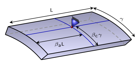
βa = Axial offset factor of the pivot point from one end of the pad
βc = Circumferential offset factor of the pivot point from the leading edge the pad
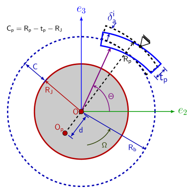
Rp = Pad outer radius
tp = Pad thickness
L = Bearing length
γ = Pad sector angle
Rb = Bearing radius
RJ = Journal radius
For the line pivot case, terms containing δic are ignored in the thickness expression.
If the pad tilt angle is already known, it can directly be specified. In many cases, the tilting is not known a priori, but rather depends on the bearing load. Moment balance for each pad due the pressure distribution of the film decides the tilt angle of the pad. The moment about the pivot point of the pad due to the film pressure is given by
After simplification, this results into the following moment balance equations for the tilt about the axial and circumferential directions:
In the above moment balance equation, pad inertia is ignored. If pad inertia is also included, the moment balance equation is modified to
where
are the components of the moment of inertia tensor of the pad about the pivot point expressed along local directions.
In the above expression, m is the mass of the pad given by
and
Expressions for the moment of inertia are derived by assuming that the shape of the pad is a sector of a hollow cylinder.
Sometimes the pads in the bearing are not completely free to tilt, but are spring loaded. In such a case, the equation of motion of the pad changes to