Intensity and Polarization
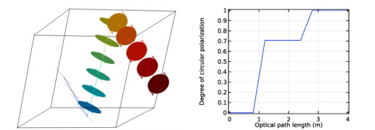
The intensity of each ray is computed by solving for a set of four variables called the Stokes parameters. Because the rays represent electromagnetic waves, in general it is often necessary to store information about the direction of the electromagnetic field vector, not just its amplitude, and the Stokes parameters accomplish this with ease.
Whenever the ray intensity is solved for in the Geometrical Optics interface, the complete state of polarization of the ray is also recorded. Any combination of different polarization states can be included in the same model, meaning that the rays can be any combination of the following:
It is important to note that ray intensity is always solved for in radiometric, not photometric, units. In other words, the intensity is represented as an energy flux in absolute terms and not the apparent flux seen by the human eye.
Reflected and Refracted Ray Intensity
Information about ray polarization is vital even to the simplest model of reflection and refraction at a material discontinuity. The coefficients of reflection and refraction depend on whether the incident ray is polarized in the plane of incidence (p-polarized) or perpendicular to it (s-polarized). This dependence is shown explicitly in the Fresnel equations,
The subscripts p and s refer to polarization in the plane of incidence and orthogonal to it, respectively; that is, p- and s-polarization.
Dielectric Coatings on Boundaries
In practice, very few refracting boundaries are simply discontinuities between two domains with different refractive indices. Most lenses and mirrors are coated with one or more thin dielectric layers that cause the reflection and transmission coefficients to differ from a simple implementation of the Fresnel coefficients.
If you know the properties of each layer in a dielectric coating — the thickness and refractive index of each layer, and the order in which the layers appear — then you can build these layers directly into the Material Discontinuity boundary condition. The Fresnel coefficients are then automatically adjusted to take each layer into account, in addition to the refractive indices of the two adjacent domains.
You can also specify that some of these dielectric layers are periodic, allowing you to quickly create multilayer coatings with tens or hundreds of layers.
Distributed Bragg Reflector (DBR): Several thin dielectric films can be added to the same boundary, and these layers can be made periodic with a large number of unit cells. Here the reflectance of a DBR with 21 dielectric layers is plotted as a function of wavelength.
The calculation of equivalent Fresnel coefficients for material discontinuities with thin dielectric coatings is based on the assumption that the layer thickness is small compared to the coherence length of the radiation, so it is best used for very thin layers of material where the thickness is known to a high degree of precision, rather than extremely thick panes of glass.
Alternatively, you can simply enter the reflectance or transmittance of a coating directly, if these are given by the manufacturer in lieu of the layer properties. The specified value need not be a constant; you can also define an arbitrary function of the ray frequency or wavelength if the light in the model is polychromatic.
Other Boundary Conditions to Control Polarization
Dedicated boundary conditions to manipulate ray intensity and polarization are available. These boundary conditions do not affect the ray direction but do modify the Stokes parameters of the outgoing ray. These include the following:
Linear Wave Retarder tutorial: An unpolarized ray (going left to right) passes through a linear polarizer, a quarter-wave retarder, and a second linear polarizer orthogonal to the first. Polarization ellipses are shown in the ray diagram. The color expression indicates the ray intensity.
Visualizing Polarization
You can see the effects of different boundary conditions on polarization by plotting polarization ellipses along each ray. These ellipses show whether the ray is linearly, circularly, or elliptically polarized. They also indicate the direction of polarization and the sense of rotation of the electric field vector, so it is easy to distinguish between left-handed and right-handed circular polarization.
Linearly polarized light is internally reflected twice in a Fresnel rhomb (left). As a result, the ray’s polarization ellipse shifts from linear, to elliptical, to circular. This can also be shown by plotting the degree of circular polarization plotted as a function of optical path length (right).