Ray Tracing Fundamentals
The most essential assumption of a ray optics approach is that the geometry is optically large, meaning that the smallest detail of the model geometry is still much larger than the wavelength of the radiation. This assumption is necessary because the Geometrical Optics interface does not include diffraction effects that occur at the wavelength scale when electromagnetic waves interact with edges or points in the surrounding geometry.
Wave propagation around an obstruction (far left) or through a slit (middle left) comparable to the wavelength produces diffraction patterns. Ray propagation around an optically large obstruction (middle right) or a wide slit (far right) produces clearly defined regions of light and shadow.
Ray Propagation
Ray propagation is controlled by the refractive index of the medium. This affects the speed at which rays propagate through the domain,
If the medium is homogeneous, or spatially uniform in each domain, then rays travel in straight lines in each medium. The rays can only change direction when they are reflected or refracted at boundaries.
Ray propagation through a lens with a homogeneous (nongraded) index.
In some cases, the refractive index varies continuously within a domain. Since the gradient of the refractive index is then nonzero, such a material is called a graded-index medium. In graded-index media, the rays can follow curved paths.
Graded-index media most often arise in coupled simulations, such as nonisothermal domains where the refractive index is temperature dependent. Graded-index media may also appear in models of chemical diffusion if the refractive index is a function of the concentration of a diluted species.
Rays follow curved paths through the graded-index medium of a Luneburg lens. The color along the rays indicates optical path length (left). The grayscale in the background is the refractive index.
Reflection and Refraction
The rays can interact with any number of boundaries in the model, in any order. It is not necessary to specify the order of the boundary interactions because the intersection points of rays with a boundary are detected nonsequentially. Based on the ray’s current position and direction, the next intersection with a surface is detected, and then the ray is extrapolated out to that surface, where the boundary condition can be applied. In a graded-index medium, it is necessary to take small, discrete steps in time (or equivalently in optical path length) to accurately predict the intersection points because the ray path can be nonlinear.
Specular reflection of rays by a corner cube retroreflector.
Whenever a ray reaches a boundary between two media with different refractive indices, the deterministic ray splitting algorithm generates a refracted ray and a specularly reflected ray. The direction of the refracted ray is computed using Snell’s law,
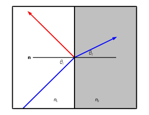
where n is the refractive index, θi is the angle of incidence with respect to the surface normal, θt is the angle of the refracted ray, and the subscripts 1 and 
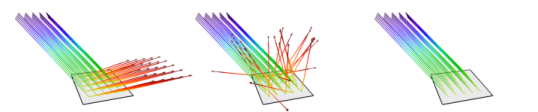
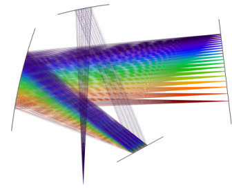
2 indicate the side of the incident and refracted ray, respectively. The ray splitting algorithm automatically also detects when rays undergo total internal reflection and suppresses the release of refracted rays accordingly.
Refraction of an incident ray (blue) at a boundary. A second, reflected ray (red) is also released.
It is easy to suppress the release of reflected rays at material discontinuities. This allows you to focus exclusively on the refracted rays in lens systems, where the stray light may not be of much interest.
Ray tracing in a pair of convex lenses. The color along the rays is proportional to the optical path length. The color in the lenses is proportional to the mesh element size. The release of reflected rays at the lens surfaces has been suppressed.
Scattering and Absorption
The default behavior of the Geometrical Optics  interface is to treat each surface as a perfectly smooth reflecting and refracting boundary between two dielectric media. Each incident ray splits into reflected and refracted rays. A wide variety of other boundary conditions can also be selected.
Any surface can reflect rays diffusely, isotropically, or specularly. Surfaces can also absorb rays; you can decide to retain the final ray position for results analysis or simply remove rays as they hit the boundary. A dedicated boundary condition for modeling reflection and refraction at random rough surfaces is also available.
It is possible to combine different boundary conditions based on a probability or logical expression. For example, you could specularly reflect 70% of rays and diffusely reflect the remaining 30%; or you could diffusely reflect rays for which x > 0 at the intersection point, and absorb all others.
Rays can be specularly reflected (left), diffusely reflected (middle), or absorbed (right) at any boundary.
Polychromatic Light
The rays in the Geometrical Optics interface are monochromatic by default but can easily be made polychromatic. You can either specify a list of frequency values or vacuum wavelength values to be released. The frequency can be an expression or an explicit list of values, or it can be sampled from a distribution.
In the Geometrical Optics interface, one mechanism for separating light of different wavelengths is to define a dispersive (wavelength-dependent) medium or use a diffraction grating.
In addition to being able to specify an initial polychromatic distribution of wavelength or frequencies, it is also possible to reinitialize these distributions at boundaries using an expression or by sampling from a distribution.
Dispersive Media
Many of the built-in materials in the Optical Material Library already define the refractive index as a function of the vacuum wavelength, using empirical data compiled from scientific literature. You can also enter user-defined expressions in which the vacuum wavelength or frequency appears explicitly. Whenever you specify the refractive index, you can choose whether the index is absolute (relative to vacuum) or relative (to air at a given reference temperature and pressure).
Alternatively, you can enter the coefficients for one of the built-in optical dispersion models, such as Sellmeier coefficients. Many glasses in the Optical Material Library use these standard optical dispersion models. Some glasses also include thermo-optic dispersion coefficients so that the refractive index becomes a function of both wavelength and temperature.
A prism containing a dispersive medium can separate light into different colors.
Diffraction Gratings
At a diffraction grating, both reflected and transmitted rays of many diffraction orders can be released. The built-in boundary condition for the diffraction grating automatically computes the direction of each of the specified diffraction orders. If you know the transmittance or reflectance associated with each order, you can specify them as well. A wavelength-scale model, solving the electromagnetic wave equation in the frequency domain, can generate this data.
Czerny–Turner Monochromator: An arrangement of collimating mirror, focusing mirror, and diffraction grating in a crossed Czerny–Turner configuration is used to split polychromatic light into separate colors. The color expression in the ray plot is proportional to the wavelength.